Exploring Your Environment with Arduino Microcontrollers
This web page supports the 2020 book by IESRE President David Brooks,
Exploring Your Environment with Arduino Microcontrollers.
The book is printed in 8-1/2" × 11"
format with a spiral binding so it will open and lie lat. The front and back covers are full color on laminated stock. The
text is entirely black and white, but full-color versions of many of the figures are available at
the link below – these full-color images are helpful for laying out the projects, invariably
on breadboards.
This book isn't intended as a tutorial on Arduino programming
(there are literally hundreds of online tutorials and books that do that),
although I have tried to explain programming concepts as they arise
and promote good
programming practices throughout the many code examples. I have paid more
attention to the opportunities and limitations provided by the large
number of sensors that are no available within the globally supported
open-source Arduino "ecosystem." I believe the book
is an excellent way to learn about environmental monitoring with Arduinos and it
could serve as a supplemental text in any STEM-related course, from upper
middle school through college.
The price for a single copy is $25 to U.S. addresses, including shipping.
For multiple copies or shipping to addresses outside the U.S.,
please contact David Brooks at brooksdr@instesre.org. All book proceeds go entirely to
support IESRE's projects.
|
|
Some comments about the book...
"I found the applications I need... more people should know about it.
Thank you for writing it and for the great job!"
ERRATA!
p. 110
SCK SPI clock digital 3
should be
SCK SPI clock digital 13
(a comment rather than an error!) In line 9 of the code in Figure 17.2, a template for using an ADS1115 A-to-D converter, the
statement defining the delay time:
const int delayTime=5000;
should be
const long int delayTime= 5000L; because the delay() function expects a long integer
rather than just an integer. It doesn't matter for delay times less than about 30,000 milliseconds, but it will for longer
delay times. Even a one-minute delay time is 60,000 ms, which does need to be specified as a long integer,
60000L. This comment applies to all code where delay times are used.
p. 107: In the "What you will need..." list for Chapter 21, and in several other places in the book,
pololu.com is misspelled polulu.com.
p. 147: Line 9 should be:
9 pinMode(TMPpin1,INPUT); pinMode(TMPpin2,INPUT);
This error doesn't affect the code because INPUT is the default mode for analog pins.
Also, there shouldn't be an "s" at the end of line 6. The code in the file containing code from the book,
linked below, is correct.
|
Supporting information for users of the book:
HERE is a sample chapter from the book.
Text file containing all the code from the book.
Web page containing full color versions of many figures in the book.
Updates and other thoughts:
- May 10, 2022: Monitoring CO2
Measuring gas concentrations with inexpensive Arduino-compatible sensors
is not easy! There are several "MQ" VOC sensors for Arduinos for detecting
various gasses. I'm not too fond of them because they require burn-in periods,
aren't particularly sensitive to just one gas, and I suspect there
are long-term calibration issues.
The SCD-40 from adafruit.com (ID 5187), with an I2C interface, is advertised as
"a photoacoustic 'true' CO2 sensor that will tell you the CO2
PPM (parts-per-million) composition of ambient air.
Unlike the
SGP30, this sensor isn't approximating it from VOC gas concentration -
it really is measuring the CO2 concentration! That means it's bigger
and more expensive, but it is the real thing. Perfect for
environmental sensing, scientific experiments, air quality
and ventilation studies, and more."
I'm not sure what kind of "environmental sensing" is envisioned for this
device, because its range and accuracy are given as "400-2000 ppm with an accuracy
of ±(50 ppm + 5% of reading)." Outdoor atmospheric levels for "greenhouse
gas" CO2 concentrations are currently around 415 ppm. THose levels vary by only
a few ppm during the year and the average levels (now at record highs!)
have been rising by only about
2 ppm per year for many decades.
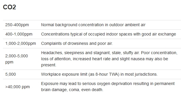
High CO2 levels can have health consequences – see, for example,
HERE:
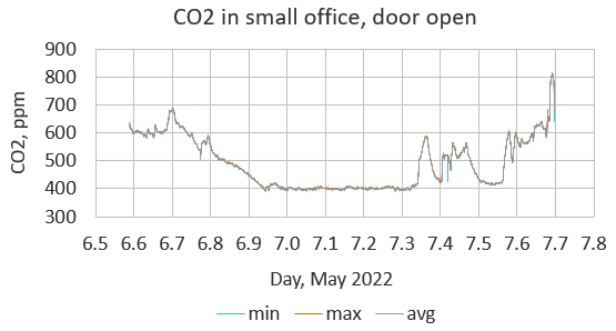
Here's some data from my home office. The CO2 levels vary from
about 400 ppm during the night when there's nobody in the office to as
much as 800 ppm during the day when I'm in the office. The graphed
data include the minimum, maximum, and average values over 12 samples,
at about one-minute intervals.
The fact that
on this scale differences between these three values
aren't distinguishable in the graph
means simply that the CO2 values don't change or vary rapidly during
this one-minute interval.
This is an interesting device for monitoring indoor CO2 levels and its
I2C interface makes it easy to use with the software library that's provided.
Considering that people breathing are a source of indoor CO2,
it's possible that having many people in a small confined space might raise CO2 levels to values of
concern.
Are these kinds of data worth the
$50 price? That's up to you!
-
February 22, 2022: Measuring the Local Sound Environment
HERE is a document that shows how to use an Arduino-
compatible dBA sound meter board to monitor the local sound environment.
In principle, it should be possible to relate noise levels to sources
of airborne particulates such as construction activity and traffic. This
measurement is especially interesting for communities where there is a lot
of construction and traffic.
-
January 17, 2022: Reducing power requirements for particulate monitoring systems
Postings in March and April, 2020, below, and Chapter 15 discussed
using Plantower airborne particulate monitoring sensors. In outdoor applications
it's often desired to run these systems continuously. Because of the fan in
the particulate sensor, this is a relatively high-power system for Arduinos (5 V at ~75 mA).
These systems will run from solar/battery power controllers, but
there may be power drop-outs in winter months with short days preceded by
cloudy daytime conditions that prevent your battery from completely charging.
Of course, you can fix this problem by using a larger solar panel and
a larger
battery. A less expensive solution may be to use an on/off timer board like
the TPL5110, available from adafruit.com (ID 3435), sparkfun.com (PRT-15353),
and other sources, as discussed in Chapter 21. The Adafruit version of these boards
(which is the one I use) has
a small on-board potentiometer that can be adjusted to set the "off" time.
In its "on" mode, the board passes the system operating
voltage (5 V for UNOs
and many others) through to the system board, which then executes
code in the setup() function. There must not be any
code in the loop() function.
When the setup() function code is finished,
a signal is sent back to the timer board, which
then shuts down the system and starts the timing cycle again. During its
"off" cycle, the timer board draws only a few microamps. Therefore, for
projects where data needs to be collected only intermittently (a few minutes
is adequate for many environmental measurements, including particulate monitoring),
this solution can greatly
reduce the system power requirements over time.
The
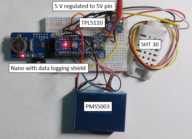
code for this project shows how to use a TPL5110 with a system using a PMS5003 particulate
sensor and an SHT30 T/RH I2C sensor. In continuously powered systems, the
loop() function is used to average a specified number of
particulate readings because it's not a good idea to record just the first data set from
that sensor. Of course, the loop() function automatically
cycles continuously through reading data streams from the PMS5003 that are sent about once
per second.
With a timer-board-powered system, code to duplicate this cycling must be built
into the setup() function. Since just one averaged data set
is collected during an "on" cycle, it's essential to include
a "warmup" delay at the top of the setup() function
to give the PMS5003 fan time to get up to speed and draw air through the
particle detection chamber; this is required to get reliable data.
"Real" programmers discourage
any use of the goto statement available in the
Arduino programming language, but I have used it
in my code for this project because it's a perfectly straightforward way to implement the
required cycling effect in the setup() function.
Although the code for continuously powered systems would typically include a header
line as the first line in the output file to identify what's in each column
of the data stored in a
.CSV file, that's a bad idea for an on/off system because each
"on" cycle appends new data onto an existing file and you don't want every data line
preceded by a header line.
When you upload any code using the TPL5110 timer board, you MUST disconnect the
timer board from the system before you do that. Then reconnect and apply
the system supply voltage to the timer board
to start collecting data. Pressing the button on the timer board will start
the timing cycle, but this should happen automatically when you apply power.
When I built and
tested this system, I used an Arduino Nano, which may require a little less power than an UNO.
(See the July 24, 2021, posting for an image of a data logging shield for Nanos,
available online, and see
HERE for a Nano pin out diagram.) The image shows the breadboard layout for this system, with the LED
lit for each module in the "system on" state. The voltage applied to the timer
board's VDD/GND pins must
be a regulated-5 V because that's the voltage passed through to power the
system directly through the 5V pin. (The VIN pin is connected to the on-board voltage regulator and
should be in the 7-10 V range.)
- January 10, 2022: u8x8 fonts for text-only data display
I have often used the u8x8 text-only library for displaying data from Arduino projects, often
on a small OLED. These devices have pixel-based libraries for simple graphics,
but a text-only subset of this
larger library is often all that's required. The default font used in the library is small
and may be hard to read on some devices.
HERE IS a list of MANY
available fonts, including some larger ones.
-
January 10, 2022: Tracking surface colors for environmental monitoring?
For environmental monitoring,
especially from space, the color of natural surfaces contains information about the
nature and possibly the health of the surface. For example, the greenness of a vegetated
surface as viewed from above can be related to the health of that vegetation.
THIS DOCUMENT provides a brief introduction to using an Arduino-compatible
RGB reflected light sensor. Can it be used to characterize the color of natural or manmade
surfaces? The cited document is only a starting point for answering this question!
-
January 6, 2022: Another option for temperature and relative humidity measurements
The August 4, 2021, posting below discussed using a SHT30 T/RH sensor from adafruit.com
and other sources as a replacement for the DHT22. As discussed in that post,
the SHT30 has a
standard I2C interface and because of its packaging I believed that it might be somewhat
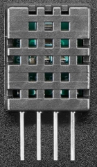
more reliable in long-term outdoor use. The new DHT20, shown here, looks like it's in
packaging identical to the DHT22 but it has a new T/RH chip, a standard I2C interface
with a software library
from Adafruit, and it's half the price ($4.50) of an SHT30 ($9) or DHT22 ($10)
from Adafruit. It's true
that DHT22 sensors are available for less from offshore sources, but if you need the smaller
packaging of the DHT22, the very reasonably priced DHT20 from Adafruit would
be a much better choice. Whether the long-term performance in outdoor applications is better
than the DHT22 remains to be seen...
-
November 15, 2021: Arduino-Based UV Measurements
HERE is a link to a long document about monitoring UV radiation with inexpensive
Arduino-compatible sensors. Vendor information supplied with such sensors almost always
misrepresents the capabilities of such sensors for calculating accurate values of the
UV index (UVI). Devices that use a single photodiode detector to represent the entire
UV radiation spectrum cannot be expected to produce accurate UVI values across
a range of sun and sky conditions. Nonetheless, there are still a few useful devices
for monitoring diurnal
variability in UV radiation and they may still provide some approximate UVI information.
-
September 12, 2021: More about processing output from analog sensors
Starting with Chapter 5, "Measuring and Displaying Air Temperatures," the book contains
many examples of using output from analog sensors. Appendix 5 deals with improving the accuracy
of analog sensors.
THIS PDF DOCUMENT provides a stand-alone resource for interpreting analog voltages, including
the use of an ADS1115 board as described in Chapter 17. The default code:
V_analog = V_digitized*5.0/1023.;
for 5 V boards like the UNO is suitable for only the most casual use of analog sensors.
-
August 4, 2021: A better temperature/relative humidity sensor?
Chapter 11, A "One Wire" Temperature and Humidity Sensor, introduces
the DHT22 (AM2302) sensor, a widely used and relatively inexpensive (~$10 or less)
device that uses a non-standard "one wire" communication protocol. As
noted in my book, there are problems with inexpensive humidity sensors
because they tend to deteriorate over time, sometimes quickly,
when subjected to long-term
exposure in outdoor weather stations. For example, the BME280 temperature, relative
humidity, and pressure sensor has the same problem. These are capacitive
sensors and what happens is that the dielectric material that forms the
capacitor gets saturated with moisture under high humidity conditions
and doesn't dry out when the humidity falls.
The SHT3x sensors from Sensirion, headquartered in Switzerland, may provide a better
solution for measuring relative humidity. From a U.S. source like adafruit.com,
the SHT30, shown below, costs less ($9)
than a DHT22 ($10). Unlike the DHT22 for which a pullup resistor must usually be
included in your circuit, SHT30 pullups are built in. SHT30s are widely
available online from
offshore sources for $5 or less. Because it uses a standard I2C interface, it
will work with any microcontroller that supports I2C, including all Arduino and
ESP8266 or ESP32 boards. ("Timing issues" with DHTxx sensors sometimes can cause
communication problems with some microcontrollers.) The I2C address is fixed at 0x44.
I suppose that a possible downside of this sensor relative to a DHT22 is its size.
The
total length of a DHT22 is about 1" (2.5 cm), while the SHT30 is about 2.25" (6 cm) long.
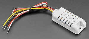
Whether this is a problem depends on your application. The image below shows
one of these sensors with four
stranded wire leads that need to be soldered to solid wires for use with breadboards or
board headers. The I2C connections are:
RED → 3.3 or 5 V; BLACK → GND; WHITE → SDA; YELLOW → SCL
An interesting feature of the SHT30 sensor
is that it includes an internal heater that
can be turned on and off with commands included as part of the supporting
library:
sht31.heater(true);
sht31.heater(false);
The purpose of the heater is to evaporate condensation and dry out the dielectric
material.
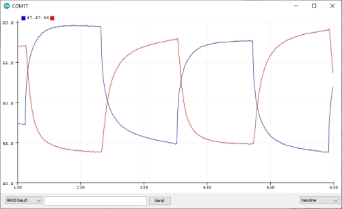
It's unclear from the documentation for this device
about under what conditions the heater should be used or for how long it should
be turned on. Of course, when the heater is on, the reported temperature will rise and
the humidity reading will decrease below the actual value in the surrounding
environment. This image shows output from an
Arduino sketch that turns the heater on and off about once every two minutes and
graphs the results about once per second using the Aduino IDE's Serial Plotter
capability. The temperature in degrees C is multiplied by 2 to scale the graphed
values closer to the relative humidity values.
When the heater is turned on, the temperature rises and the humidity falls.
(This test was done indoors rather than under outdoor high humidity conditions.)
Both the temperature and relative humidity approach equilibrium conditions after a
couple of minutes. So this indicates
that in response to prolonged exposure to high humidity conditions, it makes
sense to heat the device for two or three minutes before proceeding to collect
and log data. This capability
should greatly improve the long-term
performance of these sensors.
There's also a "reset" function, sht31.reset();. I'm not sure what its purpose
is, but perhaps you might use it after running through a heater cycle.
To get the library, which includes example code,
use Sketch→Include Library→Manage Libraries→
and type adafruit sht31
(yes, "31" gets the appropriate library) and install it.
I've not yet tested the long-term performance of these SHT30 sensors,
but other capactive sensor configurations
like the more expensive mesh-enclosed SHT30 or AM2315 from Adafruit and other sources have
proven more reliable in
long-term outdoor applications than PCB-mounted sensors; this SHT30 sensor, with its larger size for
better air circulation, will hopefully be
an improvement over other inexpensive humidity sensors. In any case, except for possible space limitations,
for new projects I can see no reason to use either DHT22 or the even less accurate DHT11
sensors.
- July 24, 2021: Data logging modules for Arduino boards
A data logging shield for UNOs was a major product offering from Adafruit.com
introduced several years ago.
That board makes it easy to record data with a date and time stamp – a basic capability
for any kind of environmental monitoring. More recently, Adafruit came out with a new
version of their data logging shield, but I was never able to get it to work
because the Arduino IDE wouldn't even recognize its real time clock as an I2C device.
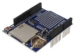
Fortunately, there are now online sources for UNO-compatible data logging shields
that are physically and functionally identical to the "old" Adafruit shield. I used
THIS SOURCE, from Chinese company HiLetGo and available from Amazon (which solves the sometimes
very long shipping times from offshore vendors). This board uses the same
DS1307 clock module that was used on the old Adafruit module (which is no longer
available) and it's about
half the cost.
Bear in mind that due to restrictions
on shipping lithium batteries, the shield doesn't include the required C1220 coin cell
battery, which is widely available. However, it does come with pre-installed
stacking headers, which must be purchased
separately for the Adafruit shield.
A revewer has pointed out that the 10-pin header on
the digital pin side of the data logger module doesn't actually connect to the
SDA/SCL pins below on the
UNO – only pins A4 and A5 provide I2C inputs. With breadboard setups, this
isn't really a problem because all SDA/SCL connections can be fed to A4 and A5.
Other reviewers have complained that this module has poor build quality,
isn't "exactly" like the old Adafruit
module, and no documentation is supplied. However, the Adafruit data logging
library works perfectly well with this module. One reviewer noted that the clock
module uses a "resonator" rather than a "crystal" oscillator. However, any DS1307
module will lose or gain time because its crystal isn't temperature compensated.
On one of my systems, used in an outdoor weather station, the clock has gained
several minutes over the course of a few months. Whether this is a problem or not
depends on your application. You can, of course, always reset the clock date/time
by including the clock "reset" statement in your sketch and reloading the sketch.
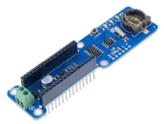
But what about boards that aren't configured like the UNO? It's possible to
buy separate SD card and real time clock modules. But there are more convenient
alternatives. These two very inexpensive modules ($2-$3) are from
aliexpress.com.
An Arduino NANO fits on top of
this module. The micro SD card holder is underneath the board in this view.
This module works with any Arduino board that supports SPI and I2C devices.
It includes a header that can be soldered for use on a breadboard. Alternatively,
you can just solder wires – all 8 are required. For use with UNOs
and other boards like the ProMini or NANO, the pin connections are:
Ground and power to a 5 V pin
SPI clock, digital #13; MISO, #12,
MOSI, #11, CS (the SD card pin), #10
SDA/SCL to SDA/SCL pins on Arduino board.
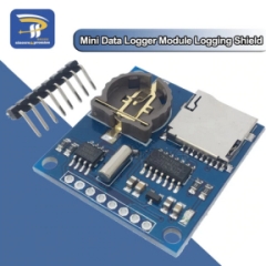
None of these modules include the
CR1220 coin cell battery required for the clock or an SD or micro SD card. It's
perhaps ironic that buying these two components elsewhere will cost more than the module itself.
These devices are so inexpensive that they make the May 14 posting, below, kind of
pointless; just the DS1302 clock module from AllElectronics costs more than either
of these complete data logging modules. I have left that posting in place only because
it has some code for programming a DS1302 clock module.
You might reasonably be
suspicious of these modules because of their prices. As is invariably
the case with these kinds of inexpensive offshore products, build quality
is a potential issue. I have used all three of the
modules described here and I have not had problems with any of them.
At this price
you can order several to allow for some quality control
problems. Finally, you might
have issues with using Chinese products that in many cases seem obviously to be
unlicensed copies
of U.S. product designs, but that's an individual (or perhaps
institutional) decision. In general, the "open source" nature of the global Arduino
enterprise for both hardware and software actually encourages competition
to keep prices down.
- June 3, 2021: Update on how to get SunFounder LCD library
Chapter 8 introduces I2C devices by showing how to use an LCD with an I2C interface.
The link for finding the SunFounder software library for the device used in that
chapter needs to be updated.
HERE IT IS.
The link to the download is near the bottom of this webpage.
- May 14, 2021: A cheap data logging module
Starting in Chapter 10, the book makes extensive use of the adafruit.com ID 1141
UNO-compatible data logging shield for recording date/time stamped environmental data.
I have used many of these shields. Although
they aren't very expensive ($14), they
won't work with other Arduinos like the NANO or Pro Mini. Fortunately, you can build your
own very inexpensive data logging "module" on a mini breadboard. For this project I used
these components from allelectronics.com:
SDR-7 micro SD card reader, $2.85
ME-48 DS1302 real time clock (RTC) module, $3.00
PB-470 pack of 5 mini breadboards, $5.00
There are many online sources for these components, but I have used allelectronics.com as a
reliable source for many years. These "offshore" devices are bigger than similar products from
a place like adafruit.com, and that may or may not be a problem depending on your application.
The only other thing you will need for this project
is some M/M jumper wires or #22 AWG
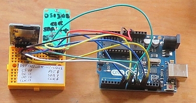
solid wire for connecting the card reader and RTC to your Arduino. Here's the module wired to
an UNO just for testing (without a card in the micro SD slot). Without the stuck-on paper label showing how to wire the modules,
there's a little
room on the mini breadboard for some other components.
The DS1302 isn't compatible with newer RTCs like the DS1307 and it isn't even an I2C
device – it takes three wires to communicate rather than just two.
So, you need to download and manually install a library written for this RTC. The
DS1302 doesn't allow you to set the date and time by accessing your
computer system's clock, so you have to manually enter the date and time just before you
upload the sketch, using a value for seconds that's a few seconds into the future to allow
time for the upload. After that, like other RTCs, this device will retain the date and time for
many months (years?) with the coin cell that's included with the module from allelectronics.com.
/* DS1302_RTC_version1, D. Brooks, May 2021
  The DS1302 is an old real time clock module predating the DS1307 and others.
  See allelectronics.com CAT #ME-48 ($3.00 including battery)and this library:
  https://github.com/hickey/arduino/tree/master/Libraries/DateTime/DateTime
  The library won't set the date/time from a computer system's clock, so you
  must manually enter the appropriate values by reading a display of your
  system's clock. It's not an I2C device. For this code: CLK-->6,DAT-->7,RST-->8
*/
#include <MyRealTimeClock.h>
MyRealTimeClock myRTC(6, 7, 8); // Assign Digital Pins
int DayOfWeek;
void setup() {
  Serial.begin(9600);
  // Read values from system clock screen display.
  // Add a few seconds to account for upload time.
  // (sec, min, hr, day of week (1-7), day, mon, day, year)
  myRTC.setDS1302Time(0, 19, 16, 3, 11, 5, 2021);
  // This code displays date in U.S. format: month/day/year
}
void loop() {
  Serial.print("Current Date / Time: ");
  DayOfWeek=(myRTC.dayofweek);
  //Serial.print(DayOfWeek); Serial.print(' ');
  switch(DayOfWeek) {
    case 1: Serial.print("Sun "); break;
    case 2: Serial.print("Mon "); break;
    case 3: Serial.print("Tue "); break;
    case 4: Serial.print("Wed "); break;
    case 5: Serial.print("Thu "); break;
    case 6: Serial.print("Fri "); break;
    case 7: Serial.print("Sat "); break;
  }
  Serial.print(myRTC.month); Serial.print("/");
  Serial.print(myRTC.dayofmonth); Serial.print("/");
  Serial.print(myRTC.year); Serial.print(" ");
  Serial.print(myRTC.hours); Serial.print(":");
  Serial.print(myRTC.minutes); Serial.print(":");
  Serial.println(myRTC.seconds); delay( 5000);
}
Here's a data logging template using these components. It's similar to the
code found in Chapter 10, but written specifically for the DS1302 module.
/* DataLogTemplate_DS1302.ino, D. Brooks, May 2021
  Template code for using microSD and DS1302 boards for
  data logging with date/time stamp.
  NOTE: Libraries that work with the newer DS1307 and other RTC
  modules will NOT work with the DS1302.
*/
#include <Wire.h> // if you will attach an I2C sensor
#include <SD.h>
#include <MyRealTimeClock.h>
MyRealTimeClock myRTC(6, 7, 8);
// SDpin is "CS" on SD module. It could be assigned to a different pin.
const int SDpin=10,DelayTime=5000;
File logfile;
char filename[]="LOG_TEST.CSV";
int YR,MON,DAY,HR,MIN,SEC;
float DayFrac;
void setup(void)
{
  Serial.begin(9600);
  Wire.begin();
  if (!SD.begin(SDpin)) {Serial.println("Card failed.");
    delay(50);exit(0);
  }
  Serial.println("card initialized.");
  logfile = SD.open(filename, FILE_WRITE);
  if (!logfile) {
    Serial.println("Couldn't create file."); delay(50); exit(0);
  }
  Serial.print("Logging to file "); Serial.println(filename);
  // Optionally, write header line here, with logfile.flush() uncommented.
  // logfile.flush();
}
void loop(void)
{
  // Get date and time.
  myRTC.updateTime(); // Reads current date/time, doesn't "update" time.
  YR=myRTC.year; MON=myRTC.month; DAY=myRTC.dayofmonth;
  HR=myRTC.hours; MIN=myRTC.minutes; SEC=myRTC.seconds;
  logfile.print(YR); logfile.print('/'); logfile.print(MON); logfile.print('/');
  logfile.print(DAY); logfile.print(','); logfile.print(HR); logfile.print(':');
  logfile.print(MIN); logfile.print(':'); logfile.print(SEC);logfile.print(',');
  // Write day expressed as decimal fraction.
  DayFrac=DAY+HR/24.+MIN/1440.+SEC/86400.;
  logfile.print(DayFrac,6);
  // Write other data here...
  logfile.println(); logfile.flush(); delay(DelayTime);
  Serial.print(YR); Serial.print('/'); Serial.print(MON); Serial.print('/');
  Serial.print(DAY); Serial.print(','); Serial.print(HR); Serial.print(':');
  Serial.print(MIN); Serial.print(':'); Serial.print(SEC);Serial.print(',');
  // Write day expressed as decimal fraction.
  Serial.print(DayFrac,6);
  Serial.println(); delay(DelayTime);
}
- April 2, 2021: More about PMS5003 particulate monitoring kit
A link to a document for constructing a Plantower PMS5003 particulate monitor with
data logging is found in the March 30, 2020, posting below. Here's an update showing the kit
constructed in a smaller case.
A note of caution about assembling this kit. Soldered connections to the DHT22 T/RH sensor
must be done VERY carefully, as the leads are fragile. They can easily be broken and will
actually break away from the housing if they are over-heated. You must bend small "hooks" in the DHT22
pins and their associated wires, crimp them together with needle nose pliers and solder
the wires as quickly as possible
without making prolonged contact with your soldering iron. Wait a minute or so between soldering
each of the wires to avoid prolonged heating of the DHT22 assembly.
This is a particulat problem for
connecting one end of a pullup resistor along with a wire to the power or output pin. It's
much better to solder just the power and output wires to their DHT22 pins. Then strip away
insulation
a centimeter or two away from those pins to solder the pullup resistor between the power and
output pins. In this photo, one end of the pullup resistor is soldered to the power pin along
with the power wire (not the best idea, as I learned from experience that resulted in destroying
a couple of these sensors),
and the other end is soldered on the output wire, away from its connection to
the DHT22 data output pin. You could solder the pullup resistor connections to the power and
data output wires before attaching
the power and output wires to their DHT22 pins.
Finally, note that the instructions call for a 10 kΩ pullup resistor on the DHT22.
Some kits may
come with smaller values, as any value between about 5 kΩ and 10 kΩ will work.

- March 30, 2021: More about using PMS5003 particulate sensors
Recent purchases of PMS5003 sensors (see Chapter 15), came with connecting cables that
are not terminated on a labeled breadboard-friendly pc board. Here's how to wire these cables. The
cables will fit properly in only one orientation in the jack on the back of the sensor –
look at the end of the cable to see which side should be "up" in the jack. Note that the
power (5 VDC) and ground (GND) wires are black and red on the cables I got, which is backwards
from the usual colors associated with power and ground. The TX lead, going to an RX pin
on your Arduino (see the comments at the head of the code linked below),
is the 5th wire from the right
in this view. Be sure you orient the PMS5003 case as shown in the photo before you
start stripping these cable wires and soldering #22 wolid wires onto them for use in
breadboard or header connections.
The righthand image shows wiring as viewed looking down
on the case with PLANTOWER stamped on it in the upper righthand corner. Use some short
piecees of heat shrinkable tubing to protect the soldered connection between the very
thin wires from the sensor to #22 solid wire.
You can find code for testing a Plantower PMS5003
HERE. This sensor doesn't require a separate
software library, but you will almost certainly need vendor-supplied code for reading
and interpreting the data stream coming into the RX pin. Here's some output from that code,
showing data from my "clean" office with very low airborne particulates.
The "standard"
output refers to data collected at sea level atmospheric conditions.
The "environmental" output
refers to data collected perhaps at much higher elevations where the atmospheric
pressure is much lower. These data are in units of µgm/m3.
For sites near sea level, the values ahould be the same
or very nearly the same. The PM1, PM2.5 and PM10 values are cumulative, e.g., PM2.5
is for all particulates less than or equal to 2.5 microns and PM10 is all particulates
less than or equal to 10 microns.

- March 2021: Testing numerical string for bad characters.
Chapter 21 shows how to use a two-Arduino packet radio transmit/receive system to send data from
a remote data collection system to a receiver. With a power on/off timer board,
as described in Chapter 21, a system
sending sensor
data every few minutes will run for a long time – even many
months – when powered by 6 alkaline D cells in series. These systems have
proven to be very reliable, but they
will sometimes send a packet with "junk" in it; I don't know
what causes this to happen.
The problem is that for the code given in Chapter 21, whenever the receiving
system receives a packet string it always assigns a date/time and logs it to an SD card.
If you want
to graph these data in a spreadsheet (I always do!) or process them in some other way,
the junk records must first be removed manually by searching
through the .CSV file and deleting those records.
This code shows how to solve this problem by testing packet strings for junk
data before processing them.
It's based on the assumption that
a valid string of numerical data can contain only the digits 0-9, a space,
a decimal point, a comma, and a + or - sign. Junk data strings will always contain ASCII
characters not in this list.
/* BadData.ino, D. Brooks, March 2021
  Checks numerical string for bad characters, as may be received
  in packet radio string. Digits 0-9, decimal point, + or - sign,
  space, or comma are the only allowed characters.
*/
String S="-012345678#9,+ ";
void setup()
{
  Serial.begin(9600);
  if (!isValidNumber(S)) {
    Serial.println(F("bad string"));
	// Ignore this string.
  }
  else {
    Serial.println(F("good string"));
	// Process data in this string.
  }
}
void loop() {
}
boolean isValidNumber(String str){
  boolean valid;
  Serial.println("Check data: ");
  for(unsigned int i=0;i<str.length();i++) {
    Serial.print((char)str.charAt(i));
    // Allowed characters in RX string: 0-9, ',', ' ', '+', '-'
    if ((str.charAt(i)>=48&&str.charAt(i)<=57)||str.charAt(i)=='+'||str.charAt(i)==','||str.charAt(i)=='.'||str.charAt(i)=='-'||str.charAt(i)==' ') {
       valid=true;
    }
    else  {
       Serial.print(" Invalid character here: ");
       Serial.print(i); Serial.print(' '); Serial.print(str.substring(i,i+1)); Serial.println();
       valid=false; break;
    }
  }
  Serial.println();
  if(valid) return true; else return false;
}
Here's the output for the string defined in the code. Not all unallowed ASCII characters will
be printable.
Check data:
-012345678# Invalid character here: 10 #

bad string
In a packet radio application, here's how to do it. I'm not completely
convinced that the
buf[len]=0;
line is required, but otherwise the terminating character at the end of
the buffer may cause the isValidNumber()
function to tag a good string
as bad.
void loop() {
 if (rf69.available()) {
    // Should be a message for us now
    lcd.clear();
    uint8_t buf[RH_RF69_MAX_MESSAGE_LEN]; uint8_t len = sizeof(buf);
    if (rf69.recv(buf, &len)) {
      if (!len) return;String S=(char*)buf;
      buf[len]=0;
      if (!isValidNumber(S)) {
        Serial.println(F("bad string"));
      }
      else {
        Serial.println(F("good string"));
        // Do all data display, processing, and logging here.

      } // end data processing loop
    } else {
      lcd.print("Receive failed");
    }
  }
}
December 30, 2020: Solar power for "high power" Arduino environmental monitoring systems
Chapter 15 discusses a particulate monitoring system using a Plantower PMS5003 sampler. The sampler includes
a small fan that draws air through the measuring system, where airborne particles deflect light from a small laser.
The fan, which should run continously, draws about 100 mA, which makes this a relatively high-power project as
Arduino environmental monitoring projects go. Indoor systems, or systems with access to AC power,
can of course use a 9 VDC "wall wart" supply to power
the system. For outdoor projects, away from an AC power source, a solar panel/rechargeable battery
supply is the obvious choice for outdoor projects.
Solar systems for this purpose consist of three components: (1) a solar panel; (2) a rechargeable battery;
(3) a solar controller. For low-power systems, LiPo systems are often used. Otherwise, lead-acid batteries are
often used. The solar panel is used to power a solar controller. During daylight hours, the controller simultaneously
powers attached devices and charges the battery. At night, battery power automatically takes over and keeps the system
running until sunlight is again available.
This three-component power system must be sized appropriately for the task at hand. DFRobot (www.dfrobot.com)
offers several controllers. For this project I used the DFR0580, $20 at the time
this document was being written. This device has screw terminals for a standard
12 VDC solar panel (with a nominal 18-22 V no-load output voltage), a 12 V sealed lead-acid (SLA) bettery,
and multiple outputs, including screw terminals and USB A connectors
for 5 V output; the regulated
output is actually 5.2 V, which is perfectly OK for powering 5 V devices like an Arduino UNO. DFRobot is a Chinese
company and there may be long shipping delays. It's also possible that some institutions won't allow purchase
of products directly from Chinese suppliers. It's possible that some solar controllers designed for
use with LiPo batteries would work for this particulate monitoring project, but I haven't tried them.
LiPo batteries are expensive and they are
not good choices for use in sub-freezing weather that always occurs in the winter where I live.
Note that lead-acid batteries can also be subjected to some operating conditions that may not allow their use in all situations.
The description provided by batterymart.com, where I got the battery used for this project, states that
their lead-acid batteries
"may be discharged
over a temperature range of -40 °C to +60 °C (-40 °F to +140 °F), and
charged at temperatures ranging from -20 °C to +50 °C (4 °F to +122 °F)." Although it's not common for temperatures to fall below
4°F where I live, it sometimes happens. This temperature limitation appears to be due to the possibility of
overcharging in very cold temperatures. However, the solar controller should prevent overcharging under any conditions, so I doubt
this will be a problem at any temperature that will be encountered where I live.
This DFRobot controller is more than up to the task of powering a particulate monitoring system.
The system variables
are the solar panel and battery specifications required to keep the system running 24/7 during
darkness and cloudy days.
I used a 2.3Ah SLA battery from batterymart.com (SLA-12V2-3). Just about any "standard" 12 V solar panel capable of producing
several watts should do.
I used a 12 V 10 W panel from AllElectronics.com, CAT# SPL-010, that I already had, to which
I added a mounting bracket to the panel frame, made from
1/4"×1" aluminum bar stock. There are other better and less expensive solar panel alternatives, such as the Newpowa 30 W 12 V panel,
SKKU NPA305-12H,
$38.58 with free shipping.
The system is shown below – obviously not with all components to scale.
This system can be tested indoors with a fully charged battery by putting the solar panel up against a
window that gets some sun. But not surprisingly, this would not keep the battery charged
with the solar panel against the west-facing
double-glazed
window in my office; such a system needs to be
outdoors in direct sunlight for it to keep a battery charged. (The solar management board itself requires some small
amount of power to do its job and for its system status indicator LEDs.)
Some of the power outputs on the solar management board can be turned on or off with a jumper; a small green LED lights when the
output is "on."
The maximum power point transfer (MPPT) switch should be on for the most efficient operation. There are a series of
small LEDs that
show the battery charge status, and these can be switched off once the system is installed outdoors in a location where
these LEDs wouldn't be visible anyhow. Lead-acid batteries are available in many different aH ratings from sources
such as batterymart.com.
The solar panel should come with some stranded wire cable already attached. You don't need a separate back-current diode protector,
because the solar management board already takes care of this for you. For the battery, you can use something like 22 AWG stranded
red/black "zip cord"
(like allelectronics.com CAT # WRB-22). You could also use standard lamp cord if you're careful about keeping
track of the the +/- leads. To make it easy to connect and
disconnect the battery and solar panel, I broke the leads near the solar management board screw terminals
and added blade crimp connectors. (The battery I used has what are called F1 blade terminals, as opposed to larger F2 terminals.)
It's best to use a crimping tool designed specifically for these kinds
of connectors, rather than just pliers. Blade connectors can be bought separately or in crimp connector assortments.
Connectors and crimping tools
are available online or from hardware supply stores like Lowe's or Home Depot.
The Arduino/particulate sensor system is powered from one of the solar management board's 5 V outputs,
through the UNO's 5 V power pin. (Yes, an Arduino's 5 V output pin can be used as a power input point for a regulated 5 V DC supply.)
Be careful to use only a regulated DC 5 volt input and never reverse the +/- power connection!

Here's the code for the project:
/* plantower_log, D. Brooks, December 2020
  Logs data from a Plantower PMS5003 sensor.
  A data stream is received about once per second and KNT_MAX values
  are averaged (200 samples = about 3 minutes). See also example code from Adafruit.
  Includes particle counts and conversion to PM2.5 AQI values.
*/
#define ECHO_TO_SERIAL 1
#define KNT_MAX 200
#include
SoftwareSerial pmsSerial(2, 3);
#include
#define SDpin 10
#include
#include
RTC_DS1307 rtc; // clock in old data loggers
//RTC_PCF8523 rtc; // clock in new data loggers
int knt=0,yr,mon,dy,hr,mn,sec;
float pm1=0,pm25=0,pm10=0;
float p03,p05,p10,p25,p50,p100,AQI25,AQI10
;
File logfile;
void setup() {
  rtc.begin(); Serial.begin(9600);
  pmsSerial.begin(9600);
  Serial.print(F("Initializing SD card..."));
  pinMode(SDpin,OUTPUT);
  if (!SD.begin(SDpin)) {Serial.println("Card failed.");
  delay(50);exit(0);}
  Serial.println("card initialized.");
  logfile=SD.open("PM_LOG.CSV",FILE_WRITE);
  logfile.print("yr,mon,day,hr,min,sec,day_frac,");
  logfile.println("PM1,PM2.5,PM10,AQI2.5,AQI10,p0.3,p0.5,p1.0,p2.5,p5,p10");
  logfile.flush();
  #if ECHO_TO_SERIAL
  Serial.println("day hr:min:sec PM1 PM2.5 PM10");
  #endif // ECHO_TO_SERIAL
}
struct pms5003data {
uint16_t framelen;
uint16_t pm10_standard, pm25_standard, pm100_standard;
uint16_t pm10_env, pm25_env, pm100_env;
uint16_t particles_03um,particles_05um,particles_10um;
uint16_t particles_25um,particles_50um,particles_100um;
uint16_t unused; uint16_t checksum;
};
struct pms5003data data;
void loop() {
  if (readPMSdata(&pmsSerial)) { // reading data was successful!
    pm1+=data.pm10_env; pm25+=data.pm25_env; pm10+=data.pm100_env;
    p03+=data.particles_03um; p05+=data.particles_05um;
    p10+=data.particles_10um; p25+=data.particles_25um;
    p50+=data.particles_50um; p100+=data.particles_100um;
    knt++;
    if (knt==KNT_MAX) {
      DateTime now=rtc.now();
      yr=now.year(); mon=now.month(); dy=now.day();
      hr=now.hour(); mn=now.minute(); sec=now.second();
      pm1/=knt; pm25/=knt; pm10/=knt; p03/=knt; p05/=knt; p10/=knt;
      p25/=knt; p50/=knt; p100/=knt;
      if (pm25<=12.0) {  // Convert to AQI value.
        AQI25=(50.-0.)/(12.0-0.)*(pm25-0.0)+0.;
      }
      else if (pm25<=35.4) {
        AQI25=(100.-50.)/(35.4-12.0)*(pm25-12.0)+50.;
      }
      else if (pm25<=55.4) {
        AQI25=(150.-100.)/(55.4-35.4)*(pm25-35.4)+100.;
      }
      else if (pm25<=150.4) {
        AQI25=(200.-150.)/(150.4-55.4)*(pm25-55.4)+150.;
      }
      else if (pm25<=250.4) {
        AQI25=(300.-200.)/(250.4-150.4)*(pm25-150.4)+200.;
      }
      else if (pm25<=350.4) {
        AQI25=(400.-300.)/(350.4-250.4)*(pm25-250.4)+300.;
      }
      else if  (pm25<=500.4) {
        AQI25=(500.-400.)/(500.4-350.4)*(pm25-350.4) +400.;
      }
      else AQI25=501.;
      if (pm10<=54.) {
        AQI10=(50.-0.)/(54.-0.)*(pm10-0.)+0.;
      }
      else if (pm10<=154.) {
        AQI10=(100.-50.)/(154.-54.)*(pm10-54.)+50.;
      }
      else if (pm10<=254.) {
        AQI10=(150.-100.)/(254.-154.)*(pm10-154.)+100.;
      }
      else if (pm10<=354.) {
        AQI10=(200.-150.)/(354.-254.)*(pm10-254.)+150.;
      }
      else if (pm10<=424.) {
        AQI10=(300.-200.)/(424.-354.)*(pm10-354.)+200.;
      }
      else if (pm10<=504) {
        AQI10=(400-300)/(504.-424.)*(pm10-424.);
      }
      else if (pm10<=604.) {
        AQI10=(500.-400.)/(604.-504.)*(pm10-504.)*400.;
      }
      else AQI10=501.;
      logfile.print(yr);     logfile.print(','); logfile.print(mon);    logfile.print(',');
      logfile.print(dy);     logfile.print(','); logfile.print(hr);     logfile.print(',');
      logfile.print(mn); logfile.print(','); logfile.print(sec);    logfile.print(',');
      logfile.print(dy+hr/24.+mn/1440.+sec/86400.,5); logfile.print(',');
      logfile.print(pm1,1);   logfile.print(','); logfile.print(pm25,1);  logfile.print(',');
      logfile.print(pm10,1);  logfile.print(','); logfile.print(AQI25,0); logfile.print(',');
      logfile.print(AQI10,0); logfile.print(','); logfile.print(p03); logfile.print(',');
      logfile.print(p05); logfile.print(','); logfile.print(p10); logfile.print(',');
      logfile.print(p25); logfile.print(','); logfile.print(p50); logfile.print(',');
      logfile.println(p100); logfile.flush();
      #if ECHO_TO_SERIAL
        Serial.print(dy);Serial.print(' ');Serial.print(hr);Serial.print(':');
        Serial.print(mn);Serial.print(':');Serial.print(sec);Serial.print(' ');
        Serial.print(pm1,1);Serial.print(", ");Serial.print(pm25,1);
        Serial.print(", ");Serial.print(pm10,1);Serial.println();
      #endif // ECHO_TO_SERIAL
      pm1=0; pm25=0; pm10=0; // reset PM totals
      p03=0; p05=0; p10=0; p25=0; p50=0; p100=0; knt=0;
    }
  }
}
boolean readPMSdata(Stream *s) {
if (! s->available()) { return false; }
// Read a byte at a time until we get to the special '0x42' start-byte
if (s->peek() != 0x42) { s->read(); return false; }
// Now read all 32 bytes
if (s->available() < 32) { return false; }
uint8_t buffer[32]; uint16_t sum = 0; s->readBytes(buffer, 32);
// get checksum ready
for (uint8_t i=0; i<30; i++) { sum += buffer[i]; }
// The data comes in endiand, this solves it so it works on all platforms
uint16_t buffer_u16[15];
for (uint8_t i=0; i<15; i++) {
buffer_u16[i] = buffer[2 + i*2 + 1]; buffer_u16[i] += (buffer[2 + i*2] << 8); }
// put it into a nice struct :)
memcpy((void *)&data, (void *)buffer_u16, 30);
if (sum != data.checksum) { Serial.println("Checksum failure"); return false; }
return true; // success!
}
Here is WeatherUnderground 10-day forecast for my site. It shows a typical winter pattern with lots of cloud cover.
The forecasted cloud conditions are usually quite accurate. On January 13, for example, the forecast
called for decreasing clouds in the early afternoon and cloud cover did thin significantly as predicted,
with enough sun to make clear shadows on the ground (and, hopefully, to fully charge the battery by the end of the day).


December 17, 2020: An ArduinoBased handheld UVI meter
HERE is a link to a document about building a handheld Arduino-based UVI meter.
(See the project
at the end of Chapter 20.) It uses a Feather 32u4
development board from adafruit.com. Unfortunately, as noted in the document, the VEML6075 UV sensor used for the
project has been discontinued by its manufacturer. However, breakout boards using this inexpensive sensor (~$7)
are still available
from two vendors mentioned in the document. The project also serves as an introduction to using the 32u4
development board (which requires more effort than using an UNO, for example.) Why bother?
Because the board includes an on-board charger for a
LiPo battery, which makes it ideal for this kind of project – see
HERE.
December 11, 2020: Potential issues with I2C devices and their pullup resistors
Exmination of posts by users who are really familiar with internal hardware workings of Arduinos and I2C sensors
demonstrate that there are sometimes probems with how "pullup resistors" are included with I2C devices. These resistors
are required between the SCL and SDA lines and the device power supply to allow communications with the I2C device.
It's often the case that when I2C devices without their own internal pullup resistors are incorporated into
breakout boards, pullups are then included on the boards. But, what happens when multiple I2C devices are used on the
same system? (With the development of SparkFun's Qwiic system for easily chaining I2C devices together, using multiple
devices is easier than ever.) If each breakout board has its own pullup resistors, these resistors are then all connected
in parallel, which reduces the effective pullup resistance in the circuit. The result may be that some or all
of the I2C devices will not work reliably or may not work at all.
I haven't had this problem myself, but others have, so I mention this just as something to consider if you
are having problems with multiple I2C devices. In some cases, you can fix the problem by eliminating pullup resistors
with some of your I2C devices. See Chapter 16, for example, where two 10 kΩ easily removable
pullup resistors must be included in the
circuit for using an MLX90614 sensor, as specified in adafruit.com's documentation for this device – See Figure 16.3.
If you're using I2C devices on breakout boards, in principle it may be possible to disable pullup resistors on one or
more boards.
But these resistors are invariably very small surface mounted components
and as a practical matter trying to remove them may be more likely
to disable the board than to solve a problem unless you really know what you're doing!
(I have never tried to do it myself because I haven't ever needed to try.)
December 8, 2020: An inexpensive digital voltmeter for Arduino projects
Although most Arduino projects don't require voltage, current, or resistance measurements to get them running,
it's often very convenient
to be able to measure these values. For example, if you're running a project on a 5 V Arduino like the UNO
from a USB cable and you're doing
analog-to-digital conversions with an analog-output sensor, you need to know the voltage from the USB cable because
that's the reference voltage that's used for converting the digital value to its analog equivalent, nominally
V_analog=5.0*V_digital/1023.;
But this calculation assumes that the voltage powering the board is actually 5.0 V. The USB standard allows a cable to
provide a voltage in the 4.75–5.25 V range. So, the 5.0 in the conversion equation needs to be changed to whatever
the actual value is. (If you're powering your board with a good 5 V regulated supply, this shouldn't a problem,
but it still doesn't hurt to actually measure the voltage at the 5 V power pin.)
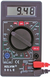
For many years, I've used these
very inexpensive 50LE digital multimeters from kelvin.com. They cost less than $5 and there are quantity discounts, making
them very attractive for classroom use or for having several of them on hand for your own use. Please note
that IESRE has no relationship of any kind with kelvin.com – this is just a comment about an instrument
I have used. |
 |
November 19, 2020: VEML6075 UV sensor discontinued
Chapter 20 discusses making UV measurements with the VEML6075 breakout board
from adafruit.com. This product has been discontinued because the VEML6075 sensor, previously manufactured by Vishay,
has been discontinued.
As of this writing, VEML6075 sensor breakout boards are still
available from sparkfun.com (SEN-15089)
and dfrobot.com (SEN0303), while their stocks last. Both these vendors provide their own software libraries. I haven't tried
it, but presumably the Adafruit VEML6075 library won't work with either of them. In any case, the libraries
are always freely downloadable, so it makes sense to use the vendor-specific library.
The Vishay VEML6070 sensor, also previously available on a breakout board from adafruit.com, has also been
discontinued. That board didn't even calculate a UV index value. The SI1145 UVI breakout board from adafruit.com
doesn't even have a UV sensor. It approximates a UVI value based on its visible and IR sensors. I'm not aware of any
replacement for the VEML6075.
August 20, 2020: One-breadboard "weather station" with Metro Mini: some opportunities and issues
First of all, "weather station" is in quote marks because this isn't really
a project about a "real" weather station. Its purpose is to:
1. show an application for the Adafruit Metro Mini UNO-compatible Arduino;
2. show an application for a 0.96" OLED;
3. discuss (once again!) issues with temperature/relative humidity sensors.
I've discussed issues with relative humidity measurements extensively in Chapter 18 of
Exploring Your
Environment with Arduino Microcontrollers. I cannot reiterate too many times that relative humidity
is VERY difficult to measure accurately and many low-cost Arduino-compatible relative humidity sensors will NOT
perform in outdoor weather stations with their typically stated accuracy of a few percent humidity
percent units. My experience is that when new, these sensors will give reasonable data, but their
performance will degrade over time – often within just a few days, depending on the weather –
when they are used in outdoor weather stations.
For this project, I've used Adafruit's Metro Mini (see the June 2020 posting, below),
an UNO-compatible board in a
small form factor. I like this board because in terms of programming, including even the selection of
"Arduino/Genuino UNO" as the board in your IDE, it's completely UNO-compatible.
Its only disadvantage is that because of its size it's not compatible with any UNO shields.
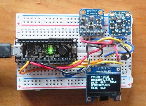
The image shows the half-size breadboard layout for this project. I used a TMP36 sensor and
BME280 T/RH/P and HTU21D-F T/RH breakout boards from adafruit.com. The BME280 is especially popular because it provides three important
weather parameters in a single inexpensive package. You can display a lot of information on this tiny
OLED from IZOKEE – see the link in the August 1, 2020 posting below for more information about
these displays.
Do these three devices give the same results? Unfortunately, no! The values are hard to read in this
image (they're actually very easy to read in reality), so here's a table of some values taken in my
office:
| Device | T | RH | P |
| TMP36 | 25.27 | | |
| BME280 | 30.63 | 64.8 | 999.9 |
| HTU21D-F | 28.91 | 50.8 | |
|
|
The barometric pressure is the "station pressure" at my site, not the "weather report" value
as referred to sea level; it is consistent with nearby values as reported online.
The temperature values vary by about 5 °C – a LARGE difference. The TMP36 value
is probably close to the
actual temperature in my office. This measurement is also of interest because the
interpretation of analog and other temperature measurements is of interest. In the code given below,
the line
T=5.*analogRead(TMPpin)/1023.;
is the standard way to convert digitized 10-bit values from a 5 V Arduino board like the UNO.
However,
This value depends on the actual voltage applied to power the board. In the image shown above, the
board is powered by a USB cable from my computer. This provides a (measured) value of 5.18 V –
well within the specs for USB power voltages. So, for this circumstance, the conversion line should
be
T=5.18*analogRead(TMPpin)/1023.;
which would have the effect of raising the temperature by a little under 1 °C.
Even though the TMP36 isn't
advertised as a particularly accurate device (±2 °C), this "corrected" value is
probably pretty close to the actual temperature in my office. If you powered this system away from your
computer with a regulated 5 VDC supply, the 5.0 value would again be appropriate.
The values from the other devices may be high because the temperature sensors on
these small breakout boards are subject to some degree of self-heating due to the power applied to the board,
even though that power is very small. In fact, the BME280's reported temperature of 30.6 °C
(87 °F) is simply much too high for the conditions in my office!
The relative humidity
values differ by about 14% – a HUGE difference that at other times increased to more than 25% higher
for the BME280.
The BME280 used here is an old device that I used for awhile
in an outdoor weather station and brought back inside a couple of months ago when it was
returning 100% relative humidity values over long periods of time when this was clearly not
the case.
I have sometimes speculated that
such devices could "recalibrate" themselves if they were brought indoors and kept in a relatively dry
and stable environment for an extended period of time. The HTU21D-F is new and never been used
before this project. Its values are more reasonable for an indoor environment, so I have to conclude
that this BME280 has not "repaired" itself!
In conclusion, a one-breadboard Metro Mini indoor weather station with a small OLED display and
a BME280 sensor never exposed to very high relative humidity conditions is
perhaps a reasonable project. But Arduino-based weather station
enthusiasts, YOU HAVE BEEN WARNED ABOUT PROBLEMS!
Here's the code for this project:
// OLED_Izokee_TEMP36_weather.ino, D. Brooks, August 2020
// Compares some data from three different sensors.
#include "U8g2lib.h"
#include "Wire.h"
#include "Adafruit_BME280.h"
#include "Adafruit_HTU21DF.h"
Adafruit_BME280 bme;
Adafruit_HTU21DF htu;
U8G2_SSD1306_128X64_NONAME_F_HW_I2C u8g2(U8G2_R0, /* reset=*/ U8X8_PIN_NONE);
const byte TMPpin=A0;
#define updateTime 3000
float T;
const int delayTime=2000;
void setup(void) {
  bme.begin(); htu.begin();
  u8g2.begin();
  u8g2.setFont(u8g2_font_ncenB08_tr); // choose a suitable font
}
void loop(void) {
  u8g2.clearBuffer();
  //----TMP36------------------
  T=5.*analogRead(TMPpin)/1023.;
  T=100.*(T-0.5);
  u8g2.drawStr(10,8,"TMP36 = ");
  u8g2.setCursor(60,8); u8g2.print(T,2);
  //Serial.println(T,2);
  //----------BME280------------
  u8g2.drawStr(10,20,"BME280 T, RH, P");
  u8g2.setCursor(10,32); u8g2.print(bme.readTemperature(),2);
  u8g2.setCursor(50,32); u8g2.print(bme.readHumidity(),1);
  u8g2.setCursor(90,32); u8g2.print(bme.readPressure()/100.,1);
  //---HTU21D-F----------------
  u8g2.drawStr(10,44,"HTU21D-F T, RH");
  u8g2.setCursor(10,56); u8g2.print(htu.readTemperature(),2);
  u8g2.setCursor(50,56); u8g2.print(htu.readHumidity(),1);
  //----------------------
  u8g2.sendBuffer();
  delay(updateTime);
  u8g2.clearDisplay();
}
August 1, 2020: Adventures with (cheap) OLED displays
|
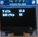
HERE's a link to a document showing how to use small and inexpensive
OLED displays. They are very low-power devices, which makes them particularly useful for
remotely powered projects. The "adventure" part comes from dealing with off-shore sources with
potential delivery and support issues. The display is actually sharper and easier to read
than it appears in this image.
|  |
July 31, 2020: A tip for using LEDs with Arduinos
|
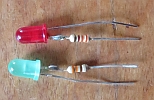
As discussed in detail in Chapter 2: Blinking Your Own LEDs, it's always necessary to use
current limiting resistors with LEDs. This is easy to do with breadboard layouts. But perhaps if you're teaching a
class on using Arduinos or in some other situation with limited time, it might be
worthwhile to prepare some LEDs ahead of time
with resistors already
attached, as shown in the image. I use 1/4 W carbon film resistors (the most common kind)
because the leads of 1/8 W resistors are very fine and hard
to use with breadboards. The resistor can be on either the positive or negative LED lead; all that matters is
that you be consistent about using the same lead every time so you won't be confused about how to hook up the LED.
I use the negative (shorter) lead to solder on a
330 Ω resistor; a smaller value like 220 Ω would also be fine. Work quickly with a hot iron, as it is
possible to destroy LEDs if you overheat them. Remember that it doesn't matter which end of the resistor is "up." |
 |
July 30, 2020: Solderless connections
|
Throughout the book I have used breadboards and jumper wires or solid wires to connect sensors to Arduinos.
Typically, that requires soldering headers or wires onto the sensor boards.
For anyone not used to soldering, this can be a chore. Recently, a
solder-free system for
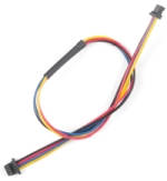
connecting sensors and Arduinos has become widely available: the Qwiic Connect System from sparkfun.com. This uses
4-pin JST connectors (all that is needed for analog output and I2C devices) to provide "plug and play" convenience.
The cables are available in various
lengths and include JST-to-breadboard cables,
too, so you can build many Arduino systems without any soldering at all. This system is available not
just with SparkFun devices, but also with devices from other vendors like adafruit.com. The four-pin cabling won't
work for all devices, specifically including SD card modules with an SPI communications
protocol that requires more than 4 pins, but it may still be an attractive option for rapid system development.
|  |
July 29, 2020: (1) Find the address of an I2C device; (2) use more than one device with the same I2C address
(1)
When you buy I2C devices from reputable vendors, they will tell you what the hardware address is for that device.
Sometimes the device is fixed and sometimes it can be changed in hardware or software. In any case, you absolutely
need to know the address to use the device. It is reported online that some devices from "offshore" sources don't
tell you the address or may even have an incorrect address printed on the device. What to do??
Fortunately, there is a simple solution. I found this code online – the URL is given at the top of the
sketch. Connect your I2C device as you normally would: power, ground, SDA, and SCL. Then just run the sketch and
the hardware address will be displayed in the serial port window. As far as I know, Arduino-compatible I2C devices
always use standard 7-bit addresses.
Note that adafruit.com has compiled a list of addresses for many (but, necessarily, not all) I2C
devices:
https://learn.adafruit.com/i2c-addresses/the-list.
// https://create.arduino.cc/projecthub/abdularbi17/how-to-scan-i2c-address-in-arduino-eaadda
// Arduino I2C Scanner
// Re-writed by Arbi Abdul Jabbaar
// Using Arduino IDE 1.8.7
// Using GY-87 module for the target
// Tested on 10 September 2019
// This sketch tests the standard 7-bit addresses
// Devices with higher bit address might not be seen properly.
// ---------------------------------------------------------------- /
#include "Wire.h" //include Wire.h library
void setup()
{
  Wire.begin(); // Wire communication begin
  Serial.begin(9600); // The baudrate of Serial monitor is set in 9600
  while (!Serial); // Waiting for Serial Monitor
  Serial.println("\nI2C Scanner");
}
void loop()
{
  byte error, address; //variable for error and I2C address
  int nDevices;
  Serial.println("Scanning...");
  nDevices = 0;
  for (address = 1; address < 127; address++ )
  {
    // The i2c_scanner uses the return value of
    // the Write.endTransmisstion to see if
    // a device did acknowledge to the address.
    Wire.beginTransmission(address);
    error = Wire.endTransmission();
    if (error == 0)
    {
      Serial.print("I2C device found at address 0x");
      if (address < 16)
        Serial.print("0");
      Serial.print(address, HEX);
      Serial.println("  !");
      nDevices++;
    }
    else if (error == 4)
    {
      Serial.print("Unknown error at address 0x");
      if (address < 16)
        Serial.print("0");
      Serial.println(address, HEX);
    }
  }
  if (nDevices == 0)
    Serial.println("No I2C devices found\n");
  else
    Serial.println("done\n");
  delay(5000); // wait 5 seconds for the next I2C scan
}
(2) In Chapter 20, Measuring UV Radiation, I said that when I tried to use a VEML6075 UV
sensor along with a VEML7700 lux sensor on the same Arduino system,
it wouldn't work because both these I2C devices
have the same fixed hardware address. It turns out that there's a way around this problem!
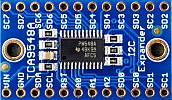
Adafruit.com's TCA9548A I2C multiplexer (ID 2717, $7) lets you get data from up to 8 same-address
I2C devices. I haven't tried it yet, but presumably it will work...
|  |
July 27, 2020: More about Arduno-compatible clock modules
You will always want to save environmental data with a date/time stamp. Many of the projects in the book assume
you will use something like the adafruit.com data logging shield, or for Arduino boards that don't have the UNO
pin layout, separate clock and SD card modules.
There are two commonly available real-time clock (RTC) modules, both supported through the adafruit.com
RTClib
library – the DS1307 and PCF8523. The DS1307 is used on the old version of the adafruit data logging shield (no longer
available) and the PCF8523 is used on the current data logging shield.
Both these devices are also available as separate modules from many sources.
The adafruit data logging shield RTC and some other RTC modules use a CR1220 coin cell battery
for power. Some other available modules may use different coin cells. In any case, these
small batteries will power the RTCs continuously for years.
RTC modules have to be initialized when they are first used, a process that sets the date and time according to
your computer's internal clock. Once set, they will keep time for a long time without ever having to
change the coin cell.
For short-duration data collection projects, these modulees keep time accurately enough for almost any environmental
measurement. However, over time, they will drift. Some systems I have kept running continuously for several
months now record times about 5 minutes ahead of the actual time – e.g., 9:35 rather than 9:30.
To fix this, you have to upload a program to reset the clock and then reload whatever data collection sketch you
are using. Remember that you can do this only if your Arduino is connected to your computer. "Resetting" the RTC
module with a remotely powered Arduino will produce a junk result! Here's a sketch you can use to reset
DS1307 or PCF8523 RTCs, assuming
you have installed the RTC library. (Be sure to select the correct module.)
For time-critical or long-duration applications, adafruit.com offers the DS3231 "precision" RTC module, which costs
more ($14) than the PCD8523 ($5) or DS1307 ($7.50). It uses the same library as the other modules.
/* RTC_2.ino, D. Brooks, August 2018
  This code has been modified to work with both old
  and new datalogging shields. The clock chip on the
  shields is different.
*/
#include "Wire.h"
#include "RTClib.h"
// RTC_DS1307 RTC; // old Adafruit data logger shield
RTC_PCF8523 RTC;  // new Adafruit data logger shield
// RTC_DS3231 rtc; // temperature-compensated clock
void setup() {
  Serial.begin(9600); Wire.begin(); RTC.begin();
  if (RTC.begin()) Serial.println("clock running...");
  else Serial.println("clock not running...");
  RTC.adjust(DateTime(__DATE__, __TIME__));
  DateTime now=RTC.now();
  Serial.println(now.year()); Serial.println("trying...");
  Serial.println("Getting time...");
  Serial.print(now.year());   Serial.print('/');
  Serial.print(now.month());  Serial.print('/');
  Serial.print(now.day());    Serial.print(' ');
  Serial.print(now.hour());   Serial.print(':');
  Serial.print(now.minute()); Serial.print(':');
  Serial.println(now.second());
}
void loop() {
}
Here's another fact about Arduino-compatible clock modules: they will keep time for years
with their coin cell backup batteries. But, they can gain or lose time during prolonged use, especially
in outdoor applications. Clock chips like the DS1307 or PCF8523 use a timing crystal whose oscillating
frequency drifts slightly as a
function of temperature. The adafruit.com data logger clock in my outdoor weather station has
gained several minutes in just
a couple of winter months. This may or may not be a problem, depending on your application. If you need a
more accurate clock, use the DS3231, whose oscillating frequency is internally temperature compensated to keep
it from drifting.
Adafruit.com, for example, has boards
using any of these three clock chips. The DS3231 board ($14) is more expensive as the other two. The
same library works for all three clock modules, as indicated in the above code.
July 22, 2020: More about using analog-output sensors
Appendix 5 discusses how to improve the Arduino's A-to-D conversion when reading data from analog sensors because
the default 10-bit 0-5 V resolution for the 5-V UNO and other 5-V boards is not good enough for many
measurements. This includes sensors like the popular TMP3x whose maximum output is small compared to 5 V.
Appendix 5 shows how to get better resolution by using the 3.3 V volt power pin or the
UNO's "internal" 1.1 V source as a reference
voltage. Some recent correspondence I had on an adafruit.com product forum about reading
analog sensors using an internal reference voltage was very enlightening.
That discussion indicated that the internal reference voltage applied to an analog pin may need some
time (a few milliseconds?) to "stabilize" before reading the pin. As a result, it was suggested that
such a pin should be
read twice, perhaps with a delay of a few milliseconds between reads. The first read is ignored and the second
would be kept. This is already a widely known strategy when reading data from more than one analog pin, one right
after the other – see the discussion and code on page 22 of the book. But the forum discussion also made
clear that this
strategy may also be desirable when reading data from just one "high impedance" sensor, regardless of what
reference voltage is applied to its input pin. Since in general I don't
have any idea whether a sensor is "high impedance" or not, it seems prudent to always apply this "two read" strategy
even when reading data from just one sensor. For the kinds of projects
described in the book, adding short delays in cases like this will never cause any problems.
July 16, 2020: Some notes about SD cards
For almost any kind of environmental montitoring, you will want to store your data for future analysis
and display. The obvious way to do this with Arduino projects is to write data along with a date/time stamp
to SD cards. This process is first described in detail in Chapter 10. The adafruit.com data logging
shield described in that chapter uses full-size SD cards. Other hardware may use microSD cards.
These days, the "standard" widely available SD card appears to be 16GB, costing roughly around
$10 and up. However, this is a LOT of storage for ASCII text data, which is the format
in which your Arduino-collected data will be stored. Even a 1 GB SD card will hold a huge amount of
ASCII data. With any data collection project, you should periodically (every few days or weeks?)
download and check your data.
Save the file on your computer and then erase the file on the SD card. If you follow this procedure you will
never come anywhere close to using 1 GB of storage!
It's possible to find 1 or 2 GB cards online for under $4 and these should be more than
adequate for any monitoring project.
Where do these cards come from? They are almost certainly from "off-shore" non-U.S. sources.
This may or may
not be a problem, although some individuals and organizations prefer not to buy from Chinese sources.
My personal preference is to buy this kind of thing from U.S. vendors even if I don't know the original
source of the product. Buying directly from no-name off-shore sources (often Chinese) can cause delivery
problems – I have sometimes waited many months to receive electronics orders from
Chinese (even Hong Kong) sources. I recently bought 1 GB cards for $3.54
each with free shipping from California-based oempcworld.com – I have no idea where the cards were made
but I received them in just a few days.
As with any electronics product, quality can be an issue and you might reasonably be
suspicious about quality from "no name" off-shore sources. I have never bought SD cards that didn't work or
failed during ongoing use with Arduinos. Newer and more expensive cards from name-brand sources tout
their high write speeds. However, this isn't necessarily a "quality" issue.
For Arduino projects there is no reason to pay extra for cards with the highest write speeds.
Do you have to format new SD cards before you use them? Almost certainly not, but it's still a good
idea to do so. On Windows computers, right-click on the SD card icon and select "format." The standard
format is 16-kB FAT. If you like, you can un-select the "quick format" option and do a full format.
This will erase whatever malware that might exist on the card.
July 15, 2020
The book contains a lot of information about recording data, but not as much about displaying
data in real time. HERE is a link to a document that
contains code for creating several different kinds of data graphs using TFT displays and the GFX
graphics library from adafruit.com. The code examples in that document use static "made up" data, but they
can be adapted to respond in real time to incoming data from sensors.
Here's a couple of examples:
July, 2020
Here are two graphs showing data from the airborne particulate monitoring system described in Chapter 15.
The sensor (in the housing shown below) is on a table on a screened porch attached to my house.
This location perhaps explains why the relative
humidity never reaches 100%. This is unusual because typically the DHT22 T/RH sensor "saturates" at high
relative humidity values when it is used in outdoor weather stations for extended periods of time. In any
event, the PM values provide a good representation of temporal variability in particulates due to
changing weather
conditions in a location where
there are no known external time-varying sources of particulates,
such as heavy traffic or industrial or agricultural activity.
(During the winter, our wood stove produces large spikes in particulate readings.)
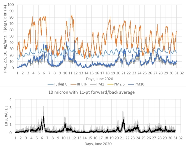
June 2020:
Chapter 22 discusses some alternatives to the Arduino UNO and one of those alternatives
is the Metro Mini from adafruit.com. The Arduino IDE recognizes this board as a "genuine UNO," so there are never
any problems with developing projects on an UNO and then moving them to a more compact board.
Instead of a USB A/B cable like the UNO, the Metro Mini uses an A/MicroB cable.
The only UNO feature the
Metro Mini lacks is a 2.1 mm power input jack. You can still power it remotely with a
9-12 VDC power supply
through the Vin
pin. Usually these "wall wart" DC supplies come with a 2.1 mm plug, which you can clip off and replace with some
AWG 22 solid wires that will plug into a breadboard (save the 2.1 mm plug for use with a battery
supply, for example!), or you can buy
breadboard-compatible 2.1 mm jacks.
The image here shows a Metro Mini with Adafruit RTC and SD card
modules for data logging. Not having a shield that fits on the Metro Mini seriously restricts
the breadboard space for attaching sensors. I have encouraged Adafruit to develop a shield
that duplicates the functionality of their
UNO data logging shield, which for many years has been my "go to" solution for reliably
recording data with a date/time stamp.
Hopefully Adafruit will at some point take this suggestion! |
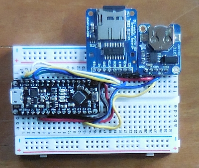 |
April 2020:
|
In collaboration with a colleague at NASA's Langley Research Center, I
developed a kit for building the
airborne particulate sensor described in Chapter 15. Parts cost around $100 – the PMS5003 particulate
sensor itself costs around $40. The case is a modified ABS plastic stock project box.
If you would like one of these kits, you can contact me at brooksdr@instesre.org.
You can find instructions for building the kit
HERE |
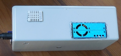 |

