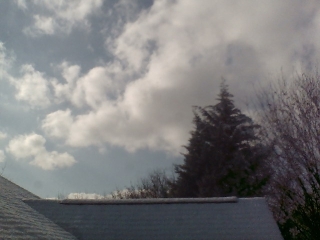
It's not difficult to create time lapse videos with an Arduino-compatible camera. Interesting projects include any phenomenon that takes place during daylight hours: the sky especially under partly cloudy conditions, snow accumulation, flood water rise, light-sensitive flowering plants, fast-growing plants such as bamboo.
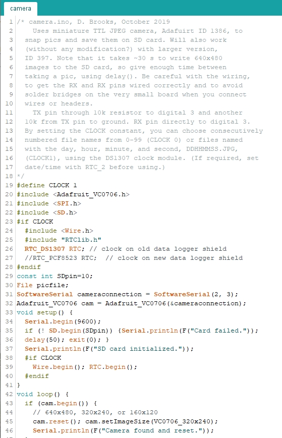
The camera shown is the smaller ID 1386. This and the ID 397 are
functionally identical and use the same software library. For this project
– creating a timelapse movie – the only
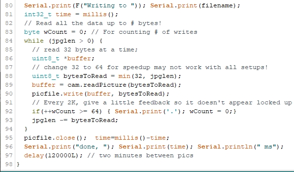
capability of interest for either of these cameras is to be able to take single
snapshots at intervals specified in your code, and store those images on a microSD
card.
There are two settings of interest for sky photography: image
size and focus. This camera stores .jpg images with code-selectable sizes of
640x480, 320x240, or 160x120 pixels. I used the 320x240 setting in my code, as there didn't
seem to be a significant advantage to using the largest image size.
The lens assembly on this unit is tiny! the black lens assembly, with its slightly
knurled circumference, is about 8 mm (5/16") in diameter.
The camera lens can be screwed in and out to change the focus
and it's supposed to come with the lens adjusted to focus
at infinity. I made the mistake of screwing the lens all the way in before testing
and I had to take several test images to return the lens to its proper spot.
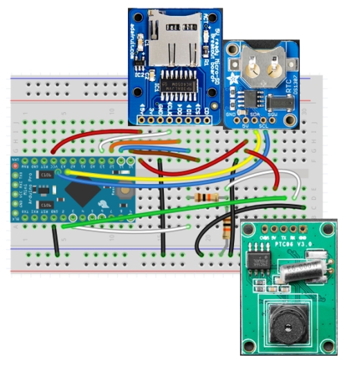
In the breadboard layout shown here I've used a Pro Mini.
Any board that supports I2C (for the clock),
SPI (for the micro SD card), and software serial (for the camera)
connections will work.
Here are the pin connections for an UNO or Pro Mini:
All boards:
VCC or 5 V power to 5 V power pins, GND to GND pins
Micro SD card module:
CS --> digital 10, DI --> digital 11
DO --> digital 12, CLK --> digital 13
Clock module:
SDA --> SDA or A4, SCL --> SCL or A5
Camera module:
RX --> A3, TX --> A2
Note that for use with a 5 V Arduino, a voltage divider (with two 10 kΩ
resistors) is used to lower voltages
sent to the camera's RX pin. If you use a 3.3 V board, the voltage divider is
not needed.
In the breadboard image,
the SD board doesn't yet have a card inserted. Even older microSD cards
with as little as 1 or 2 GB of memory will hold a LOT of data,
so it's not necessary to buy the largest available SD card.
Depending on your computer,
you may need an SD card adapter to read microSD cards.
The less expensive PCF8523 clock module is described as being
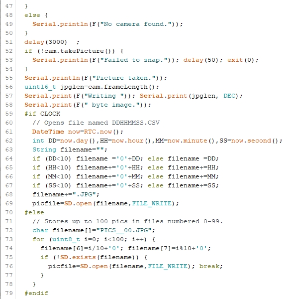
less accurate than the DS1307 module. For time lapse photos taken over a day or so,
the less expensive module is adequate. I use the DS1307 because I always have some on hand
for long-term monitoring projects. The Adafruit module is shown without its
coin cell battery. Once
you insert a coin cell and run a sketch to set the time from your computer clock
(see below),
either of these clock modules will keep time for several years with accuracies
more than adequate for this project.
Instead of installing a header on the camera module you could, of course, attach
wires that allow you to move the camera module around independent of the
breadboard.
With a Pro Mini, you will need an FTDI module and USB cable to install a
sketch and this same cable will power the system for testing. (Install a male header on
the six pins at the left end
of the board.) If you wish to
use the system away from your computer you will need an external power supply,
like a step-down regulator or a
step-up/step-down voltage regulator with a 9 V plug-in
supply or 6 C or D cells in series. If you use a power supply delivering at least 7.5 V you
could even use an LM7805 step-down regulator in a TO-92 three-pin housing. These devices
are inexpensive (~1-2$) but they are not very efficient and I generally don't bother with them.
For a battery supply, a step-up/step-down regulator is the best choice because it will
produce a 5 V output even when the battery supply voltage falls below 5 V. (When that happens
you should, in any case, replace the batteries!) Attach a 5 V
output to the Pro Mini VCC pin.
 |
 |
 |
|
|