An Arduino-Based Packet Radio Weather Station

Arduino microcontrollers are inexpensive, widely available, globally supported, open source computing platforms for controlling hardware. There are many environmental monitoring sensors that are easy to interface with Arduino boards. The goal for this project is to construct a basic weather station that:

Even if you are used to working with Arduinos, using them for stand-alone aoutdoor applications poses some additional challenges. I restarted this project several times as I learned more about converting applications that are easy to implement in a familiar indoor breadboard/Arduino UNO environment to systems that will work for reliable and sustainable outdoor applications.

Hardware

The first step is to define the equipment needed to meet the project goals. Previous projects I have developed use various sensors with Arduino UNOs. These boards are the most widely used for project development. Although they don't require much power to operate, they are not the most energy-efficient Arduino-compatible boards. Power requirements are an issue for stand-alone applications you would like to run outdoors away from a plug-in power source, unattended for long periods of time. For a power supply, my first thought was a solar-charged battery system. There are Arduino-compatible solar controllers that will charge a battery when there is sun, split off some power from the solar cell to power a device when there is sunlight, and automatically switch to battery power when there is no sun.
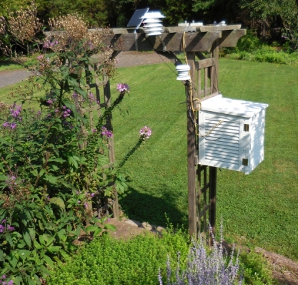
      I did, in fact, build such a system. Eventually, though, I found another approach that is very reliable and will run unattended on a 9-V battery source for many months before requiring new batteries. This system uses an Arduino Pro Mini board with a packet radio board that transmits data to an indoor Arduino UNO board with a packet radio board to receive data. Although it might seem that two separate Arduino setups would be more expensive than a single solar-charged battery-powered system with data collection and data logging all on one board, the overall cost of a packet radio system is about the same as a solar-powered system with all the sensors and data on one board. I was actually surprised at the reliability of this system, which transmits data regularly from an outside weather station about 25 m from my indoor office, through a stucco over metal lath exterior wall and several interior walls.
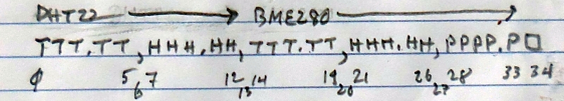
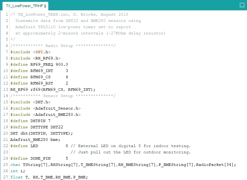
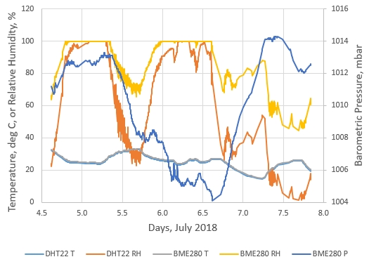
      For the weather station sensors, I chose a DHT22 temperature/relative humidity sensor and a BME280 temperature/ relative humidity/pressure sensor. With the packet radio system, the 
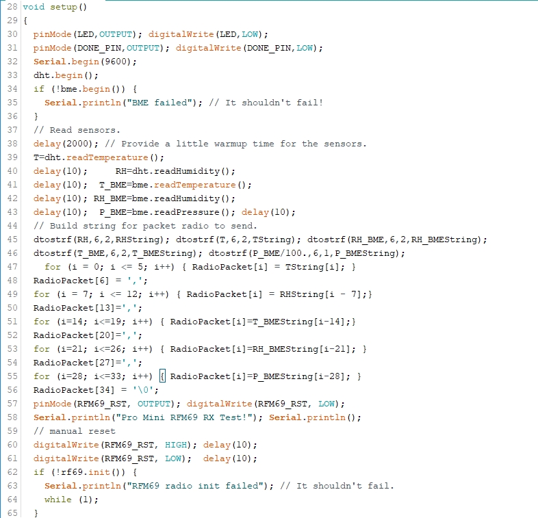
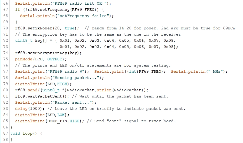
transmitting station reads data from the sensors, encodes the values into a text string (the "packet"), and sends the packet to the receiving station, which decodes the packet and handles all the data logging.
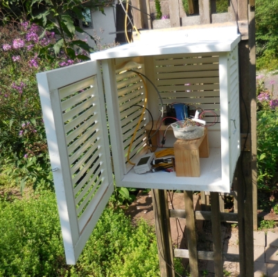
      If the transmitting station were continuously under power, it would not be very good choice for a battery-powered system. However, Adafruit (www.adafruit.com) offers a low-power timer that applies power to the Arduino system intermittently, based on adjusting the value of an on-board resistor. When the system is turned off, the timer board draws only about 20 μA! When the sensors have been read and the packet has been sent, the Arduino sends a signal back to the low-power timer, which shuts down the board and restarts the timing cycle. For this project, I set the low-power timer to turn the Arduino system on approximately once every two minutes, with the "Delay" resistor is set to about 27 kΩ The cycle time can't be set exactly by adjusting the resistor, but an approximate two-minute cycle seems reasonable for this application. (The Adafruit tutorial for the timer board gives a table of resistance and cycle time values if you wish to change it.) This system has been running for several months, through a cold winter and some very hot summer days, on a 6 alkaline D-cell battery pack; that is not a particularly small power supply, but it lasts a long time because the power drain over time is very small.
      This project assumes you have already installed the Arduino Integrated Development Environment (IDE) on your computer and you know how to use it. Here is a list of the hardware you will need for this project. Prices are approximate, as of summer 2018.

Suggested sources for packet radio project (from www.adafruit.com except as noted)
Arduino Pro Mini board, ID 2378, $10, plus stacking headers,ID 2830, $1.25, or www.sparkfun.com DEV-11113, $10, plus headers, PRT-00116, $1.50
SparkFun FTDI Basic Breakout - 5V, https://www.sparkfun.com DEV-09716, $15, plus A/miniB USB cable
or FTDI Serial TTL-232 USB cable, ID 70, $18
Arduino UNO or compatible board:
www.allelectronics.com UNO (includes USB A/B cable), #ARD-21, $14.00
www.adafruit.com ID 2488 METRO 320 with headers (doesn't include USB A/microB cable), $18
www.sparkfun.com RedBoard (doesn't include USB A/miniB cable), DEV-13975, or www.allelectronics.com #ARD-22, $20
TPL5110 low power timer board, ID 3435, $5
20×4 LCD with I2C interface, www.sunfounder.com TS0352, $15, plus 4-pin female connecting cable or M/F jumper wires (my preference) or LCD shield kit, ID 772, $20 (considerable soldering required)
Packet radio transceivers (2), ID 3070, 2 × $10 = $20
Pololu adjustable step-up/step-down voltage regulator, www.pololu.com #2119 S7V8A, $6
data logging shield, ID 1141, $14, plus CR1220 coin cell battery for clock, ID 380, $1, SD card or microSD card with adapter, ID 1294, $10
half-size breadboard, www.allelectronics.com PB-400, $4 or www.adafruit.com ID 64, $5
BME280 T/RH/P sensor, ID 2652, $20
DHT22 T/RH sensor, ID 385, $10
batteries and battery holders, www.allelectronics.com, BH-141 (4 D cells), BH-142 (2 D cells), $2 each; alkaline D cell, PRC-1300, $1.75 each
AC to 9-VDC power supply with 2.1 mm plug (for powering UNO board) ID 63, $7 (100-240 V input. U.S. plug) or www.allelectronics.com PS-914, $8 (100-240 V input with international plug set)
(miscellaneous) www.allelectronics.com, 4-pin connecting cables, M/F and M/M jumper wires, USB cables, stackable headers, Arduino UNO and Pro Mini compatible boards, etc.
(optional) Depending on what kinds of headers you have on your Arduino board and data logging shield, you may need a screw shield for connections on the receiving station: www.robotshop.com RB-lte-127, $4

      There are several sources for UNO and UNO-compatible boards and any of the listed ones are suitable. At the time this document was written, the $14 "official" Arduino UNO from www.allelectronics.com was the best deal of which I was aware. Considering these prices, I would not bother with the very inexpensive UNO clones widely available online; they are of variable quality and may not always be 100% compatible.
      A battery powered 5-V step-up/step-down voltage regulator will continue to provide a constant 5 V output even when the battery supply falls below 5 V – another reason why a 6 D-cell battery pack lasts such a long time. For this project, I have used an adjustable step-up/step-down regulator. Why? Because some "5 V" regulators may produce a voltage significantly above 5 V. My experience is that the Adafruit low power timer is very sensitive to the input voltage used to power it, and input voltages above 5 V may destroy this board. (Arduino boards and many other 5-V devices are less sensitive to input voltage. The standard for USB-powered devices is 5 V±5%.)
      You can ignore the trend toward larger and larger SD card memories. Even a 2 GB SD card will record many months of weather data.
      Some of these components are available less expensively from other than the sources shown, but consolidating sources will almost always reduce shipping costs and perhaps even total project cost. Arduino UNO boards usually include a USB A/B cable, but other compatibles may or may not include the required cable. I have used all the online sources shown here and I consider all of them to be reliable. If you are starting "from scratch" with no Arduino components, I suggest doubling up at least on Arduino boards and sensors. With two working systems, you will have a better chance of obtaining continuous data in case one system fails.

Setting Up Your Station

      The first priority for an outdoor weather station is protecting the electronics and sensors from moisture – direct precipitation and condensation. Arduino boards and most sensors are not actually rated for outdoor use, but they can be used outdoors if you are careful. The best solution is a ventilated enclosure specifically designed for weather stations. These are referred to as Stevenson screens or enclosures. Unfortunately, Stevenson screens are expensive (several hundred dollars?!).
      If you have access to woodworking tools you can make your own enclosure. The basic design is a rectangular box with louvered sides and front, a solid back and floor, and a louvered hinged front door. The back can also be louvered. The top slopes so water runs off. In some designs, there is a double roof, separated with spacers by an inch or so, to keep solar radiation from impinging directly on the instrument box. Inside the box, there are mounting blocks or standoffs so sensors aren't in direct contact with any box surface.
      If you make your own screen, use 3/4" pine or exterior plywood for the frame, roof, and floor (painted white inside and out). Making your own wood louvered shutters is not particularly easy. Wood is the best material, but vinyl shutters will be much less expensive. If you use commercial shutters, then the size of your box (which is not critical) will be determined by available shutter sizes. I used 15" wide x 36" high molded vinyl shutter panels. I cut the panels apart and braced them with wood strips to make louvers for all four sides of the enclosure. (See HERE for a short description of the Stevenson screen I built.)
      An alternative to a Stevenson Screen is to mount the Arduino hardware in a moisture-protected enclosure and run cables to sensors in a commercially available "inverted pie plate" radiation shield. Two of these shields are shown in the left-hand image below, but they are not used for this project. (One of them is a commercial product and the larger one is one I made from microwavable plastic potato bakers from a dollar store.) Considering the cost of Stevenson screens, this seems like an attractive option. However, I do not recommend this because these shields will not protect sensors from wind-blown rain. The DHT22 or BME280 sensors, with their exposed components and circuitry, should never be exposed to direct contact with moisture. Even if you used a radiation shield, you will still need a weather-protected enclosure for other equipment.
      Even with a Stevenson screen, you may still encounter moisture condensation under some weather conditions or moisture from wind-blown rain. If your system starts to produce junk values or stops working altogether, moisture is the most likely culprit. My experience is that, while moisture can destroy an Arduino board, you may be able to rescue your system by taking it indoors and letting it dry out before powering it up again.
      Of course, it is better to do all you can to avoid moisture problems ahead of time. I put my transmitter board in a small plastic tub with some cat litter. Obviously, it doesn't make any sense to "protect" a humidity sensor by placing it in that artificially dry environment, so I put the two sensors on a separate small breadboard connected to the transmitter board with jumper wires.
      The images below show my Stevenson screen mounted on a trellis with the transmitter board in its tub with cat litter, the sensors (behind the tub), and the 6 D cell battery supply (in back). The yellow cable and data logger are for a different project.

Arduino hardware connections

      There is little point to measuring weather parameters unless you can record them along with a date and time stamp. The transmitting system uses a Pro Mini. The receiving system uses a UNO or compatible with an Adafruit data logging shield (see parts list above) that includes a calendar clock whose date and time is set by your computer clock and an SD card interface for storing data.
      Here is the breadboard layout for the transmitting system. Some, but not all of the packet radio pins can be reassigned; there is no reason to do that. As with any code that interacts with hardware, pin specifications given in the code must match the hardware connections. This breadboard layout was for initial testing. As noted above, I later moved the sensors onto their own breadboard, connected to the transmitter board with jumpers.
For the DHT22: power pin to Pro Mini VCC, ground to GND, and output to digital pin 8, with 10kΩ "pull up" resistor connected between the power and output pins.

For the BME280: VIN to VCC, GND to GND, SDI to Pro Mini SDA, and SCK to SCL

For the packet radio:

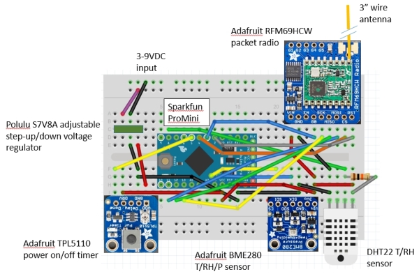
packet radio --> Pro Mini
5V           --> VCC
GND          --> GND
CLK          --> digital 13
MISO         --> digital 12
MOSI         --> digital 11
CS           --> digital 4
G0           --> digital 3
RST          --> digital 2
For the power on/off timer:
timer --> Pro Mini
VDD   --> 5 V from external power supply, no more than 5.00 V!
GND   --> GND
DRV   --> VCC
Done  --> digital 5
Delay --> Measure resistance to ground (without power) to set on/off power cycle, about 27 kΩ for 2-minute cycle
The packet radio pin connections for the receiving system are the same as for the transmitting system except the 5 V pin power pin goes directly to the 5 V Arduino header pin. On the receiver, the LCD connections are ground, power, SDA to analog 4, and SCL to analog 5. For this system I used a screw shield to connect all the wires because that is a little more secure than just using the headers. Three of the wire colors on the four-pin female connector I attached to the LCD's I2C interface board pins didn't match the colors I wanted to use to attach to the UNO, so I spliced other wires with the colors I wanted: red for power, black for ground, yellow for SDA, and blue for SCL.
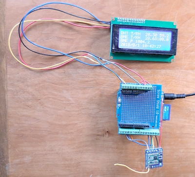
      On the transmitter, the DHT22 with its pull-up resistor is the white rectangular object in the lower right hand corner of the transmitter breadboard and the BME280 is next to it. The low power timer is the board in the lower left-hand corner of the breadboard. The voltage regulator on the left side of the breadboard powers the timer board, not the Pro Mini directly. The timer board's DRV pin sends its 5-V output to the Pro Mini's VCC pin, which also powers the sensors. A "done" signal from digital pin 5 on the Pro Mini turns power off until the next power-on cycle.
Packet radio transmitterPacket radio receiver with LCD and data logger

      At some point you may be tempted to replace a breadboard-based system with something more permanent, and there are items like the Adafruit Perma-Proto breadboard, ID 1609, that will let you do this. It is reasonable to "hard wire" some connections on such a board, but it is a mistake to hard-wire Arduino boards and sensors. These relatively inexpensive devices will not last forever. They may get wet and need to be dried, or dirty and need to be cleaned off. Breadboard and header connections are, in general, very reliable. It is much better to make these devices easily removable and replaceable as needed.

Powering your packet radio transmitter

      I have used 6 1.5 V alkaline D cells wired in series to power the packet radio transmitter system using an adjustable buck-up/buck-down regulator to power the timer board. With this buck-up/buck-down regulator, 4 cells will work just as well because the regulator will continue working even if the voltage output from the input source falls below 5 V. C cells should also work. Even AA batteries might work, but I would not bother with them for long-term operation. Carbon-zinc batteries are much cheaper than alkaline batteries and they may also work perfectly well in this very low-power application.
      As noted above, the output of the regulator should be adjusted to be no more than 5.00 V because of my unfortunate experiences with destroying timer boards with input voltages even a little above 5.0 V; I have set the output of my voltage regulator to about 4.95 V.

Arduino code

      This document assumes you already have access to the freeware Arduino Integrated Development Environment (IDE) and that you know something about Arduino programming. If you have no prior programming experience, or have never programmed an Arduino before, you can find literally hundreds of books and online tutorials about the Arduino programming language. The packet radio boards, DHT22 and BME280 sensors, and data logging shield with its real-time clock and SD card interfaces, all require their own software libraries. If you don't know how to install libraries containing the required .cpp and .h files, you can get help online. Basically, all that is required is to download and copy the (free) required files into appropriately named folders in your Arduino libraries folder when there are no Arduino sketches open. Then, when you open a sketch that requires these libraries, they will automatically be recognized when you include the .h file names in your sketch.
      The DHT22 sensor is a "one wire" device and the BME280 T/RH/pressure sensor is an I2C device. For the DHT22, "one wire" is in quote marks because although this device requires only one data pin for communication with an Arduino board, it doesn't conform to the "Dallas one-wire" communication standard. It doesn't have a unique device address, so multiple DHT22 sensors would require connection to separate digital pins. Like all I2C devices, the BME280 uses the SCL and SDA pins for communication. That sensor can share communications through the SCL and SDA pins with other I2C devices that have different preset or programmable hardware addresses. (In principle, address conflicts are possible, but I have never found one.)
      All the packet radio code for transmitting and receiving data, none of which is obvious to casual programmers, is based on examples Adafruit provides with the required software libraries.

Packet radio transmitter code

      The code includes some output to a serial port for testing. When your system works properly you can comment out some of the the serial port output before moving the system outdoors. It won't hurt anything if you leave the serial port output statements, but there is no need for them and it takes a little extra time to process these commands when there is no serial port window to receive the output.
      The radio packet transmission code consists of four sections:

1. Include the required sensor and packet radio libraries, define some pins and variables, and initiate the radio driver and sensors.
2. Read values from the DHT22 and BME280 sensors.
3. Build packet string by converting the numerical sensor values to strings of characters, using the dtostrf() function.
4. Send the packet and, when succesesful, send a "turn off power" signal to the on/off timer.

It may be helpful to sketch out the contents of the packet string before writing the code. I have chosen to represent temperature and relative humidities in XXX.XX format and barometric pressure in XXXX.X format. The first character is at position 0. The square box at the end of the line is the end-of-string character '\0' at position 34. See lines 45–56 in the code. You will have to know the layout of the packet string when you decode it in the receiver code.


      When you upload the transmitter code to the Pro Mini you must use the FTDI connector – see the parts listing, above. The FTDI connector powers the board and provides the USB connection for communicating with the Pro Mini. When you do this, you must disconnect the timer board from the circuit. Once the code is uploaded, you should be able to see some output displayed in the serial port window, including the "one shot" sensor values that will be used to form the packet string. Then you can disconnect the FTDI connector, reinstall the timer board, and supply power to the timer board through your voltage regulator.
      There is some status and error handling code in this sketch, which sends messages to the serial port window. My experience is that once the system is known to be commumicating properly with a receiver, errors simply don't occur. Having said that, the nice thing about having an outdoor transmitter separate from an indoor receiver is that you can keep an eye on the receiver's LCD, which displays the date and time of the last received packet string. If the display isn't updating properly, or if the data look odd, then you know something is wrong with the transmitter. With a self-contained system data collection and recording system outside in your weather station, you won't know anything is wrong until you power down the system, exchange the SD card, and look at the data file on the card you just removed.
      Note that in this Arduino sketch there are no repeated operations in the loop() function, although that function must still be included in the code even if it is empty. Steps 2–4 are performed once in the setup() function when the system is powered up. When the steps are completed, the system sends a power-down signal to the timer board and those steps aren't executed again until the next power-on cycle.

Packet radio receiver code

      The packet radio receiver code consists of three sections:

1. Include the required packet radio, real time clock, SD card, and LCD libraries, define some pins and variables, and initiate the radio driver and LCD devices in the setup() function.
2. Put the packet radio in "listen" mode, and wait for a packet string in the loop() function.
3. When a packet is received, decode the string, display the results on the LCD, and write data to a .CSV file the SD card.

      Step 3 is in the loop() function, which continuously listens for a new packet. Like the transmit code, this code also includes some output to a serial port window, for testing. This can be turned off by commenting out those lines, but for this "inside" system, presumably under continuous power from a DC power supply plugged into a wall outlet, there are no system power issues and nothing wrong with leaving the serial output code turned on even if the receiver board isn't connected to a computer.
      It is important to remember that the packet string just sends characters. The sensor data "values" that are displayed on the LCD and written to the SD card are still just characters and not numbers. There is no need to try to convert the characters in the received packet string back into numbers. When you write these characters into a comma-delimited text file (for opening directly in a spreadsheet), those characters will look like, and be properly interpreted as, numerical values. The fact that the sensor data are reported as strings of characters rather than numbers means that you can't do any numerical processing of the data inside the receiver code, which is why the assumption is that you will do all the data processing in another application like a spreadsheet.
      Arduino file names are limited to 8 characters plus a 3-character file type. They will not have an accurate date/time stamp as you would normally expect. When you copy these files to your computer and open them in a spreadsheet, when you save them they will then have the expected date/time stamp.

Data from Packet Radio Station

      Here are some data from July 2018. The temperature values from the DHT22 and BME280 sensors are essentially the same and the small differences, almost always less than 1°C, aren't visible in this graph. However, there are extreme differences in the relative humidity values! This is not surprising for relatively inexpensive sensors, because measuring relative humidity accurately is very difficult. The principle behind the sensors is to measure "absolute" moisture in the air and then apply a temperature-based correction to provide relative humidity. Which values shown here are correct? It is not easy to tell, but the very low values from the DHT22 sensor, approaching 0% on July 7, are very suspicious and unlikely to be accurate, especially during relatively humid summer weather conditions. It is worth pointing out again that neither of these sensors are intended for continous outdoor use. Whether the relative humidity sensors could be recalibrated periodically against a more reliable standard is unknown, but I am not optimistic.
      The barometric pressure values are not "weather report" pressures, corrected to sea level, but the actual "station pressures" for this site at an elevation of about 130 m.

Some Concluding Remarks

      Given the popularity of solar-battery systems for outdoor Arduino applications, I was somewhat surprised to find that the battery-powered packet radio system described in this document was, in the end, my first choice for a simple and reliable weather station. It is easy to dismiss the value of a battery-powered system because we expect batteries will need to be replaced more often than we consider convenient. As noted above, this has not been a problem with the low-power timer board used for the transmitter station because the 6 D-cell power pack lasts for months under a range of weather conditions.
      This is not a perfect system. Every now and then, the transmitter stops sending data, or the receiver stops receiving and recording data. Sometimes these problems can be fixed by restarting the systems. Occasionally, breadboard connections can fail, possibly as a result of some moisture-induced corrosion. When I first set up the transmitter outdoors in a Stevenson screen, the transmitter problems appeared to be moisture-related. The procedure described above, with the transmitter board surrounded by some cat litter and the sensors on a separate breadboard and connected to the transmitter board with jumper wires, is still being tested. It should minimize moisture-related problems.
      You should periodically check your battery supply. Testing battery voltage under a "no load" condition, when the battery isn't actually supplying power, is not necessarily a good test of how the battery is operating. A little dampness in and around battery holders can be a problem. If you are having transmitter problems, make sure your battery supply is completely dry. Take it indoors to dry everything out, or replace the supply entirely.
      It is possible that in some cases you might have to reinstall the transmitter and/or receiver code. If you reload the transmitter code, be sure to remove the timer board from the circuit before you do that!
      As noted previously, neither the DHT22 nor BME280 sensors are actually rated for continuous outdoor use by their manufacturers. These inexpensive sensors are widely advertised as being suitable for Arduino-based weather stations, but this is not an accurate or fair message to consumers. There is a reason they are inexpensive! In outdoor applications, they will eventually fail over a time scale measured in months, or perhaps even weeks, rather than years. The relative humidity sensor is the most vulnerable, as repeated exposure to very high humidity conditions causes the sensor to deteriorate. In my system, the DHT22 RH sensor has been reasonably consistent over several months, if not necessarily very accurate. On the other hand, after several weeks, the RH sensor on one BME280 sensor started returning a value of 100% all the time, and before that, values that were much too high to be reasonable. I do not believe that erratic DHT22 or BME280 sensors can be "fixed" just by drying them out, so you may have to accept the necessity to replace these sensors on a regular basis.
      These system problems and failures are inconvenient, for sure, but for me they do not diminish the overall value of this system. They do clearly make the point that inexpensive sensors, especially for relative humidity, are problematic in the long term when used in any weather station application.
      Battery status and occasional glitches aside, systems like this shouldn't go completely untended for many months even if you don't observe any problems. With my system, a periodic check during the summer revealed a wasp's nest in the Stevenson enclosure (yes, I got stung!). This and other potential bug problems (spiders, for example) already argue for regular maintenance. In this context, very occasionally replacing batteries is a minor (and relatively inexpensive) matter!
      I do not know the maximum working distance between transmitter and receiver. As noted above, my system is about 25 m from my house. it is possible to replace the simple 3" wire antenna with a more sophisticated antenna, but I do not know under what conditions this might be required.
      It is possible to add more low-power sensors to this system. It is tempting to add light and UV sensors available from sources liked Adafruitor SparkFun, but you would have to devise a way of mounting them outside your enclosure where they will "see" the sky while at the same time be protected from moisture – not a simple problem!. In any case, additional sensors can be added just by including their libraries, if needed, and extending the packet string to encode the output values.
      Of course, it is also possible to use this system for monitoring indoor temperature and relative humidity. Where power is readily available, there is no reason not to use a 9-VDC supply rather than a battery to power the on/off timer. You could also rewrite code to eliminate the need for an on/off timer. To do this you will need to put all the sensor and packet-creation code that now resides in the setup() loop into the loop() function, with some delay() functions to send data at the desired interval. The receiver code would remain the same.
      You can find the Arduino code for this project here: PacketRadioCode.txt.

Extending Your Weather Measurements: Monitoring Insolation

      Insolation is the total incoming solar radiation measured on a horizontal plane at Earth's surface, in units of watts per square meter (W/m2). Instruments that measure insolation are called pyranometers. These instruments can also measure solar radiation in other orientations, in the plane of solar photovoltaic or water heating panels, for example, to measure solar input available to those devices. Laboratory grade pyranometers can cost several thousands of dollars. Less expensive versions use silicon photodiode detectors. These instruments might more accurately be called "surrogate pyranometers" because they do not respond uniformly across the wavelength of incoming solar radiation. Nonetheless, they are widely used in research and agricultural applications.
      Silicon photodiode pyranometers are analog devices that don't require a power source and typically produce a few tenths of a volt in full summer sunlight. With an output in this range, the built-in 0-5 V, 10-bit analog-to-digital resolution available on Arduino analog input pins is inadequate for this measurement. It is true that the 0-5 V full scale range can be reduced somewhat by using a lower external reference voltage, but that doesn't really solve the problem of insufficient A/D resolution.
      Fortunately, there is a simple and not very expensive solution to this problem: the ADS1115 4-channel, 16-bit programmable gain board from Adafruit (ID 1085, $15). Connection to an Arduino is easy because it is an I2C device. Here is a breadboard layout using, like the previous layout, a Pro Mini, low-power timer, and packet radio, plus the ADS1115 board at the bottom of the breadboard. The inputs are labeled A0-A3, not to be confused with the analog pin numbers on an Arduino – the four channels are all available through the I2C connection to allow multiplication by a calibration constant specific for each pyranometer. The receiver layout is exactly the same as for the weather station project. You can find more information about high-resolution Arduino-based data loggers on IESRE's website, www.instesre.org.
      For this project, I have used two silicon photodiode pyranometers – an SP-Lite pyranometer from Kipp & Zonen (around $400) and an inexpensive pyranometer developed by IESRE ($75 assembled and calibrated or $25 in kit form). See http://www.instesre.org/construction/pyranometer/pyranometer.htm for information about building your own pyranometer from a kit supplied by IESRE. That web web page shows a special cable for connecting to a commercial data logger. For this project, you need only two-wire microphone (audio) cable with short pieces of solid hookup wire soldered on the ends for inserting into a breadboard. (Depending on the gauge, stranded wires may be difficult to use with breadboards even if the ends are twisted tightly and "tinned" with solder.)
      The code for this project is similar to the previous code for sending and receiving packets. The receiver code defines some strings using the Arduino's String object to allow operations such as string concatenation and extracting floating point numerical values from a character string. The transmitting code just sends as characters the voltage values read from channels A0 and A1 of the ADS1115 board, set for a range of 0–0.256 V. The conversion to an insolation value is done in the receiving code by multiplying voltage by a calibration constant for each pyranometer, which is why numerical values must be extracted from the string of characters in the packet string.
      Although I have used commercial data loggers for many years, the advantage of this Arduino-based packet radio project is the same as for the basic weather station described above: system performance can be monitored in real time and insolation data can be conveniently displayed indoors on an LCD while also being saved on an SD card.

Testing the Adafruit TPL5110 Low Power Timer Board

      Because I have had problems with the TPL5110 low power timer boards, I put together a breadboard circuit designed specifically to test that board with a Pro Mini. I powered the adjustable step-up/step-down voltage regulator from a 9-VDC supply and set its output to the timer board to just a few millivolts under 5 V. I connected an LED in series with a current limiting resistor from digital pin 4 to ground and turned it on for two seconds for every power-on cycle. (You could also use the on-board LED on digital pin 13.) For this setup, I clipped off the SHDN pin on the voltage regulator because it's not needed and it would have interfered with the power pin to the LED in this crowded breadboard setup.

/* PowerTimerTest.ino, D. Brooks, August 2018
Connections on Pro Mini: "Done" to digital 5 timer board's "DRV" to VCC LED to digital 4 through resistor to ground Use Polulu adjustable step-up/step-down voltage regulator to power timer, output no more than 5 V. You could also just use pin 13 to power the on-board LED. */ const int donePin=5, LEDpin=4; void setup() { // Power is applied... pinMode(donePin,OUTPUT); pinMode(LEDpin,OUTPUT); digitalWrite(donePin,LOW); digitalWrite(LEDpin,HIGH); delay(2000); digitalWrite(LEDpin,LOW); digitalWrite(donePin,HIGH); // turn off power } void loop() { }