Interfacing a "MightyOhm" Geiger Counter with an Arduino UNO:
An Example of Using Arduino Hardware Interrupts
I recently bought a Geiger counter kit from
MightyOhm because it was on sale along
with a nice laser-cut acrylic case. To be clear, neither IESRE nor I, personally. have any financial or
other business relationship with MightyOhm. I'm writing about this product simply because it's an interesting
measurement and an interesting introduction to Arduino interrupt procesesing. With the Geiger tube supplied,
this device measures beta and gamma radiation,
but not alpha radiation. It's advertized as a "hackable" kit with a couple of options
for interfacing with external devices. I wanted to use the simplest option to communicate
with an Arduino without needing any
additional hardware. (The other option requires a special cable to provide serial communications.)
Geiger counters measure "ionizing radiation" – charged particles or photons emitted from radioactive atomi nucleii. Naturally
occurring sources include uranium, thorium, radium, and radon gas, all of which are present everywhere on Earth
in small quantities. Naturally occurring ionizing radiation levels aren't usually considered as posing a human health
hazard. Radon gas is produced from rocks in the ground, with levels depending on the underlying geology; it
can pose a significant health hazard if it's allowed to accumulate inside
closed structures, including homes; in those cases radon remediation may be recommended. (It's not believed
that
Geiger counters can be used as monitors for potentially harmful radon levels.) Beta radiation takes the form
of an electron or positron emitted from decaying atomic
nucleii. Gamma radiation consists of photons emitted from unstable nucleii.
(See
HERE, for example.)
Geiger counters contain a sealed tube (called a Geiger tube or a Geiger-Mueller tube) filled with an
inert gas such as argon, helium, or neon, plus a small quantity of some other gas that
is described as a "quench gas" to prevent multiple pulsing from a single detection event.
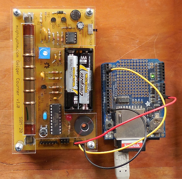
The MightyOhm Geiger counter uses
an SBM-20 tube with two electrodes to which 400 VDC is applied. (Yes, the MIghtyOhm Geiger counter contains circuitry
that boosts its 3 V battery supply voltage to a very low-current 400 V.) When ionizing radiation penetrates the
tube, some molecules are ionized and these create an "electron avalanche" that generates an output
pulse. For a more detailed description see HERE,
for example.
These SBM-20 tubes are not new devices. Huge quantities were made in the Soviet Union in the 70's through the 90's.
They are
widely available from many online sources. Why were so many of them made and why are they so easily available (for
around US$40 or so)? I don't know.
When the MightyOhm Geiger counter detects a radiation event, it emits a short beep, flashes an LED, and sends
a ~100 µs positive voltage pulse to one of its output pins. It's this pulse (a couple of volts?) that
provides a signal an Arduino can use to
count the number of detected radiation events. Often, results are reported
as counts per minute (CPM).
How do we tell an Arduino (I used an UNO) to look for these randomly occurring events?
It won't work to attach the pulse output signal to an input pin and look for a positive voltage spike in the
loop()
function because while the loop is cycling through
whatever code is in that function, it will probably never detect the very short voltage pulse.
What we want is for the Arduino to do nothing except
constantly monitor
an input pin for a positive pulse. This is a classic use for Arduino hardware interrupts.
No additional hardware is required to communicate with the Geiger counter except for three
M/F jumper wires or a 3-connector 0.1"-spaced female cable to connect the Geiger counter to
your Arduino. For saving the data I used the SD card interface on an UNO data logging shield from
adafruit.com (Part ID 1141) that I already had; I didn't need the real time clock on this shield.
You can also use a separate SD card interface. If you work with Arduinos, you may already have what you need.
If not, you can get everything you need from a place like AllElectronics.com:
- M/F jumper wires (10-pack): JMF6-10, $6.95
- micro SD card interface: SDR-7, $2.85
- Arduino UNO with USB A/B cable: ARD-21, $14.00
The Arduino code to do this is not difficult if you look online for some sketches using
hardware interrupts. Two of the pins on the three-pin
header that provides the pulse output (labeled J6 on the Geiger counter board)
are for the pulse and ground. The third pin is for input of ~3 VDC to power the
Geoger counter; this voltage can be provided from the UNO's 3.3 V output pin. (On its own, the Geiger
counter is powered by 2 AAA batteries in series and it delivers ~3 V to this pin.)
Arduino UNOs have two pins – digital 2 and 3 – that can serve as interrupt pins.
Activity on these pins is monitored by using a specialized function called an Interrupt Service
Routine (ISR). These routines accept no inputs and can send no outputs through a
return statement. All variables must be defined locally or
already exist as global variables.
The interrupt routine in UNO code can look for one of four conditions on an interrupt pin:
- LOW, when a voltage goes low
- CHANGE, whenever the value on the pin changes
- RISING, when the pin goes from low to high
- FALLING, when the pin goes from high to low
For this project, RISING is the appropriate choice,
to catch the "leading edge" of the event pulse.
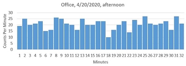
Here's the Geiger counter/Arduino setup and some counts-per-minute data from my office.
The data for the graph comes from the GEIGER2.CSV file created by the project code.
You can find more information about Arduino hardware interrupts
HERE and elsewhere online. Here's the sketch I wrote for this project. There are several
commented-out lines I used when I was testing the code, where I displayed and recorded every event. I
called the Interrupt Service Routine isr, but you can give it any
name you like.
/* geiger2.ino, D. Brooks, April 2020
  Counts and records pulses output from MightyOhm Geiger counter.
  Calculates counts per minuts (CPM) based on tracking output from
  millis(). Uses UNO and Adafruit data logging shield, but doesn't
  use real time clock.
  On Geiger counter J6 ("PULSE"), viewed from top of case:
    middle pin: pulse output, to D2
    "top" pin (toward battery side of case): to GND
    "bottom" pin (black triangle, toward Geiger
      tube side of case): ~3 VDC when running on battery.
      With battery off, can be used to power Geiger counter
      from UNO's 3.3 V output pin.
*/
#include
// nInterrupt=0 is for digital pin 2, 1 is for pin 3
const int SDpin=10, nInterrupt=0, interruptPin=2;
volatile int knt=0;
long unsigned int millis_start,M;
File logfile;
char filename[]="GEIGER1.CSV";
void setup() {
  Serial.begin(9600);
  if (!SD.begin(SDpin)) {Serial.println("Card failed.");
    delay(50);exit(0);
  }
  logfile = SD.open(filename, FILE_WRITE);
  if (!logfile) {
    Serial.println("Couldn't create file."); delay(50); exit(0);
  }
  Serial.print("Logging to file "); Serial.println(filename);
  pinMode(interruptPin,INPUT_PULLUP); // built-in resistor.
  attachInterrupt(nInterrupt,isr,RISING); // Start watching.
  millis_start=millis();
}
void loop() {
}
void isr() { // interrupt service routine
  knt++; M=millis();
  //Serial.print(M); Serial.print(' ');Serial.println(knt);
  //logfile.print(M); logfile.print(',');
  //logfile.print(knt);
  if ((M-millis_start)>60000L) {
    //Serial.print("CNT/min = "); Serial.println(knt);
    //logfile.print(knt);
    logfile.println(knt); // counts per minute
    knt=0; millis_start=M;
  }
  //logfile.println();
  logfile.flush();
}