Building a Thermopile Sensor
Background
 Another page on this website describes a project to continuously monitor the surface radiating temperature with an instrument using an Excelitas TPS 1T 0134 OAA060 thermopile sensor. That page shows a "breadboard" version of the instrument built on
a small piece of perfboard. This page gives instructions for building this instrument on a pc board designed specifically for this
project. A complete kit of parts is available from IESRE for $50, including shipping.
Another page on this website describes a project to continuously monitor the surface radiating temperature with an instrument using an Excelitas TPS 1T 0134 OAA060 thermopile sensor. That page shows a "breadboard" version of the instrument built on
a small piece of perfboard. This page gives instructions for building this instrument on a pc board designed specifically for this
project. A complete kit of parts is available from IESRE for $50, including shipping.
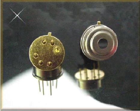 The thermopile sensors come in several different configurations. The one used here has a field of view of about 60°. It produces
a voltage output
in the range of 0-4.5 V, corresponding to a temperature range from -27°C to 60°C. (Only the most extreme polar regions
are likely to lie outside this range!)
The thermopile sensors come in several different configurations. The one used here has a field of view of about 60°. It produces
a voltage output
in the range of 0-4.5 V, corresponding to a temperature range from -27°C to 60°C. (Only the most extreme polar regions
are likely to lie outside this range!)
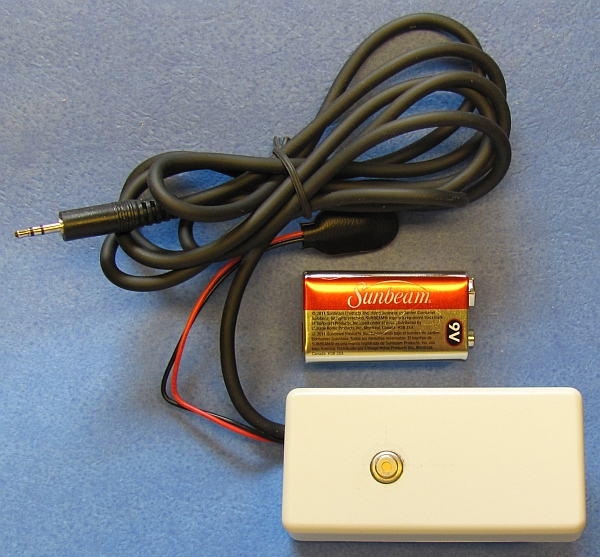
 The output cable provided with this kit is intended for use with a
HOBO U12-006 12-bit USB data logger from Onset Computer Corporation. This is the same data logger recommended for use with IESRE's pyranometers. The U12-006 logger has a range of 0—2.5 V, so the circuit described below divides the thermopile sensor output in half so as not to exceed this range. The
data logger is not provided with the kit. Other loggers may work if their range and digital resolution are sufficient to provide the required accuracy. Note that some other inexpensive data loggers may have a range of 0-10 V with only 10-bit analog-to-digital resolution, which is not sufficient for this measurement.
The output cable provided with this kit is intended for use with a
HOBO U12-006 12-bit USB data logger from Onset Computer Corporation. This is the same data logger recommended for use with IESRE's pyranometers. The U12-006 logger has a range of 0—2.5 V, so the circuit described below divides the thermopile sensor output in half so as not to exceed this range. The
data logger is not provided with the kit. Other loggers may work if their range and digital resolution are sufficient to provide the required accuracy. Note that some other inexpensive data loggers may have a range of 0-10 V with only 10-bit analog-to-digital resolution, which is not sufficient for this measurement.
Construction
Assembling this instrument requires only basic electronic construction techniques for through-hole components.
Read through all the instructions before you start construction. Tools and equipment you will need include:
- 25-40 watt soldering iron with a fine pencil tip
- small-diameter (1/32") resin-core solder (standard lead/tin or lead-free)
- small needle-nose pliers
- small diagonal cutting pliers
- small craft knife
- small squeeze tube of cyanoacrylate glue ("superglue")
- (optional) some bathtub caulk
Parts included with the kit:
- pre-drilled ABS plastic enclosure
- cable with 2.5 mm stereo plug for Onset HOBO USB data logger
- 9-V battery clip
- pc board
- 78L05 voltage regulator
- 0.1 μf ceramic disk capacitor
- (2) 40-kΩ metal film resistors
- LTC1050CN8 op amp
Parts for a data logging system that are NOT included with the kit:
- Onset data logger (see above)
- HOBOware software for data logger (must be purchased separately, Lite version is OK)
- 9-V battery (NOTE: See Use and Maintenance for alternatives)
Construction steps
| 1. Referring to the image here, install and solder in place the components shown on the top of the pc board. (Solder from
the bottom side of the board.)
The order in which you install the parts doesn't matter. The voltage regulator and capacitor should be mounted as close to the pc board as is possible without forcing the pins leads. The voltage regulator must be oriented with the flat side as shown, but the orientation of the other components doesn't matter. | 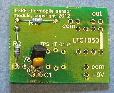 |
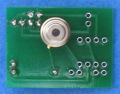
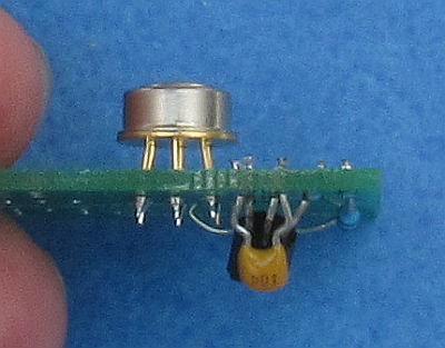
2. Turn the pc board over. Referring to the images here, install and solder in place the thermopile sensor.
Note the orientation of the tab on the thermopile sensor case and the layout of the solder points to make sure this component is oriented properly. This sensor is by far the most expensive component of this instrument (about $25 to replace just one of them), so handle it carefully! Do NOT touch the window on the top of the sensor with your fingers. Under conditions where the air is very dry, it is possible for static electricity discharges from your hand to destroy this device, so touch something metal before handling this component under those conditions.
Three of the pins are not for electrical connections, but just to stabilize this delicate component on the board. The pins are fragile, so work carefully. Align the pins in the 6 holes. Push the component throug the holes (don't touch the surface of the window on the top of the sensor) so the bottom of the thermopile sensor case is about 1/8" (0.3 cm) above the surface of the pc board.
Solder one pin in place from the top side of pc board — it doesn't matter which pin. After soldering this one pin in place, make sure the sensor case is level relative to the board and then solder the rest of the pins in place.
|
 |  |
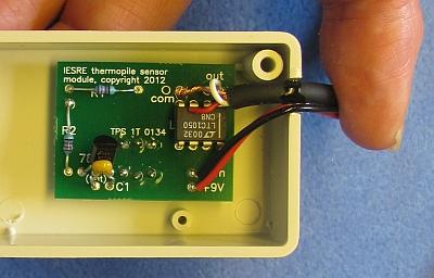
| 3. Solder in place the red and black wires from the 9-V battery clip, as shown. Connect the 9-V battery to the clip and test the operation of the thermopile sensor, using digital voltmeter leads placed as shown. Depending on temperatures and where the sensor is pointing, the output may be more than 2 or 3 V. If you point the sensor in different directions, the output voltage should change. If this is not the case, then there is something seriously wrong. Check your soldering and component placement relative to the images shown here. It is possible to destroy any of these components by overheating them, but other than that, it is very unlikely that this circuit will not work if you have followed the instructions so far! | 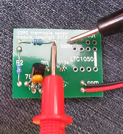 |
4. Install the op amp, as shown. Yes, the lettering on the op amp is supposed to be upside down relative to the lettering on the pc board!
Strip about 1" (2.5 cm) from the end of the 2.5-mm cable. Solder the white wire to an "out" point and the braided shield to a "com" point above the op amp, as shown. Assuming the cable is going to be used with a HOBO USB logger, the output signal must be connected to the tip of the stereo plug (the white wire for this cable). The middle ring shouldn't be connected to anything — with this cable, snip off the red wire. There are extra solder points for the output and common signal; but they are not used for anything.
Attach the 9-V battery to its clip and measure the output at the tip and bottom ring of the 2.5mm stereo plug. It should be half the value observed previously when the output from the thermopile sensor was measured directly — under no conditions you will encounter should the output exceed 2.5 V. If the op amp and output cable are installed correctly, it is highly unlikely that you will see any problem with the operation of this circuit. | 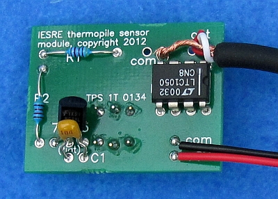 |
| 5. Place the pc board in the case so that the sensor fits in the hole in the top of the case. Working from the top, squeeze some
superglue around the circumference of the sensor case. Make sure the sensor is seated level in the hole. Be very careful not to get ANY glue on the top of the sensor case and especially on the sensor window! Getting glue on the window will destroy the calibration of the device and render it useless for accurate measurements! Hold the pc board
in place for several seconds until the glue sets and the sensor doesn't move in its hole. You could also use quick-setting two-part epoxy for this step, instead of superglue. | 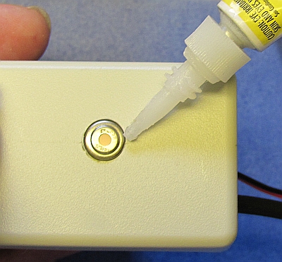 |
6. Position the battery leads and output cable in the notch in the bottom of the case. Enlarge this notch with a craft knife if required, so that the lid will fit properly over the leads and cable. Use some superglue or quick-setting epoxy to hold these wires in place.
7. Test your instrument to make sure it is responding to different surface temperatures. Fasten the lid of the case using the two screws provided, making sure to align the lid with the cutout in the rim over the cable and battery wires. Start the mounting screw in its threaded hole so it doesn't get lost.
Optionally, you might want to smear some silicone bathtub caulk around the wires coming through the case and around the edges of the case before you screw the lid onto the case. After you screw on the lid, you could smear a little caulk over the screw heads, too. Once you have tested your instrument it is unlikely that you will need to open the case in the future. But, if you do, the silicone caulk is easy to remove with a knife or even a screwdriver blade. |
 |
OTHER CONSTRUCTION OPTIONS
If you are using a data logger other than the HOBO U12-006, with a range of at least 0—4.5 V, then you could bypass the voltage divider part of the circuit (R1 and R2). However, the resistive load on the output from the thermopile sensor must be at least 50 kΩ. To do this, connect the two resistors in series across R2 and solder a jumper wire across R1. It is possible that a data logger might provide a sufficiently high resistive loading for the thermopile sensor all by itself (The U12-006 does not), without the impedance buffer provided by the LTC1050 configured as a unit-gain amplifier. In that case, you could simply connect the output from the thermopile sensor directly to the logger.
There is no on/off switch for this device, because the assumption is that you will hook up the power source and let the circuit run continuously. There is room to install a small on/off switch in the end of the case (for example, All Electronics MTS-4 or SMTS-4). If you install a switch, make sure that it is not under the screw hole in the case lid!
Use and Maintenance
The instrument should be mounted on a horizontal arm above the surface whose temperature you wish to monitor. A mounting distance of roughly 0.5—1.0 m above the surface should work well, but larger distances might be appropriate for some surfaces and research purposes — the higher the sensor is off the surface, the more it averages the radiation it sees from the surface within its field of view. This sensor
"sees" a circular area defined by a 60° field of view. If the sensor is 1 m above the surface, that circle has a diameter of about 2•[1•tan(30°)] = 1.2 m.
The instrument should be mounted level to the surface being measured but, for a homogeneous surface, it is not critical for the instrument to be exactly level — this is why the instrument does not have a leveling device on the case. The mounting arm, which should be as long as necessary to ensure that the mounting structure is outside the instrument's field of view, should (in the northern hemisphere) point south relative to the mounting structure so the shadow of the mounting structure (except for the mounting arm itself) is never inside the field of view of the instrument.
The window on the thermopile sensor should not be pointed continuously at the sky where the sun is in its field of view. The window surface should not get wet. If the unit is pointed down toward the ground, shield the top of the entire assembly from direct precipitation.
Even a high-quality alkaline 9-V battery will last only a few days in continuous operation. The circuit requires an input voltage in excess of 7 V to operate properly. Alternatives include rechargeable 9-V batteries, a 12-V solar panel, or 6 1.5-V C or D batteries in series.
The interpretation of the voltage output from this device is explained in the reference at the beginning of this article.