An Arduino-Based Low Power Indoor Weather Station with Display
David R. Brooks, January 2020
I have written extensively about collecting weather/environmental data with Arduino
microcontrollers for display and archiving. Sometimes, especially for indoor measurements, all you want is a
way to collect these data and
display them on a screen in real time.
This is very easy to do anywhere you have access to AC power for
the system, but displays like LCDs, OLEDs, or TFTs require enough power to make a small and
portable battery-powered system more of a challenge. For outdoor systems, I have used
6 D cells with a very efficient Polulu buck-up/buck-down voltage regulator and
programmable on/off timer board like Adafruit's ID 3435 TPL5110 (or the
equivalent SparkFun PRT-15353)
to power a packet radio system. This works fine, but it isn't a very practical solution for a small
portable system.
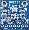
This document describes a system that uses a small Arduino UNO compatible, a BME280
temperature/relative humidity/atmospheric pressure sensor, a date/time clock module, and an
"e-paper" display from adafruit.com. This small black-and-white display works like the
"static" displays used in popular e-readers. From a power consumption point of view, the huge advantage
of these displays is that the image last written to the display stays on the display even
when power is completely disconnected. For this application, requiring only writing text to
the display, the coding is straightforward with the standard fonts available
Adafruit's GFX graphics library.
There are many inexpensive commercial products that will measure and display this kind of
information. I was interested in this project mainly because I wanted to try the relatively new
small static displays. And, of course, you can program this system to process and display data from other kinds
of sensors, like the Plantower airborne particulate sampler described
HERE.
For this project I used Adafruit's Metro Mini microcontroller not because it was
necessarily the best choice
– it's certainly not the only choice – but because it's 100% compatible with
the immensely popular UNO you don't need to install any additional board support in your
Integrated Development Environment (IDE). When using the IDE to write code
for this project, just choose the UNO ("Arduino/Genuino UNO") board. Even though the small Metro Mini
board doesn't look like an UNO
(you can't use any of the UNO shields and there's no 7-12 VDC power input jack, for example),
the IDE still recognizes it as a "genuine" UNO.
The table below shows the components I used with prices at the time I developed the project.
(The images aren't scaled to relative size.) If you don't already have one,
you will need a way to charge the
LiPo battery, like the Adafruit charger shown in the table.
If you don't already have at least some of the components, this isn't a particularly inexpensive
project; the display, which you probably don't already have, is the most expensive
component. Note
that the image on the display shown in the table isn't just a pasted-on label –
it's an image previously
programmed onto the display before it was sold and it stays there essentially permanently
until the display is powered up again and re-programmed.
You could save a few dollars by using an off-brand Pro Mini if you already have the required FTDI
connector for communicating
with your IDE, or a NANO, both widely available online from various electronic distributors.
The point of using the TPL5110 timer is simply this:
the timer shuts off all power to the rest of the system for a time based on the value
selected by a small potentiometer on the
TPL5110 board. With other kinds of displays, the display turns off when the system is powered down.
But
the display used for this project remains visible like printing on a page even
when the power is off. Therefore, you can completely shut down the entire system between data collection intervals and
not lose the display until the TPL5110 turns the system back on again for the few seconds required to read
and display new data. With this project, the system draws about 18 mA when power is on, and about 120
μA
when power is off. For a project like this, updating the indoor temperature, relative humidity,
and atmospheric
pressure shouldn't need to be done any more often than every few minutes.
Project Components
Adafruit Metro Mini UNO compatible
Adafruit ID 4197 2.13" 250x122 Monochrome eInk/ePaper Display |
$12.50
$22.50 | 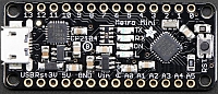 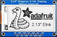 |
Adafruit ID 2652 T/RH/P sensor
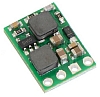
Polulu #2121 5V step-up/step-down voltage regulato
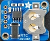
Adafruit ID 3296 DS1307 real time clock with CR1220 coin cell |
$19.95
$4.49
$7.50+$1 |
    |
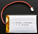
2000 mAh (Adafruit ID 2011) LiPo battery (or larger)
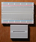
half-size and mini breadboards
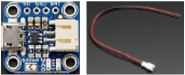
LiPo charger (like Adafruit ID 1904), 2-pin male JST cable
|
$12.50
~$3–$5
$6.95, $0.75
|
 |
|
|
Here are the power and digital pin connections for the eInk display. Some of the pin assignments can be
changed in code, but there's no reason to do that. I connected all the indicated
pins, even though some of them aren't
necessary for this project – for example, because the project doesn't
use the microSD card mounted on the back of the display board. (See the Adafruit documentation for this device.)
VIN --> 5V or VIN, GND --> GND, SCK --> 13, MISO --> 12, MOSI --> 11
ECS --> 10, D/C --> 9, SRCS --> 8, RST --> 5, BUSY --> 3
The BME280 and RTC modules are both I2C devices, with the usual 5 V power, ground,
SDA (A4 or SDA on actual UNO), and SCL (A5 or SCL on actual UNO) connections.
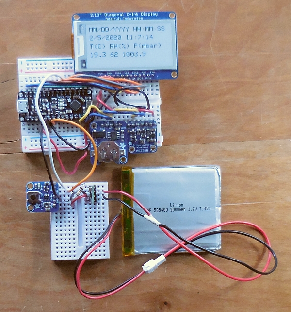
Breadboard Layout
This image shows the project breadboard layout, running from a 2000 mAh LiPo battery
through a step-up/step-down 5 V regulator connected to the timer board. For connecting the battery to the
regulator, I modified the male JST cable, as shown, by soldering some #22 solid wire to
its leads.
The timer and step-up/step-down voltage regulator
are mounted on a separate mini breadboard. Why? Because the timer board shouldn't be connected to
the system when it's being powered through the USB port, for loading code or looking at
serial port messages, and this arrangement makes it easy to disconnect the timer board/external
power source from the system when it's being powered from a USB cable. When the system is being
battery powered, through the timer board,
the "Drv" pin passes through the 5 V output from the step-up/step-down regulator to the Vin
pin on the Arduino.
Once your breadboard setup is working, you could hard-wire all of these connections and mount everything
more compactly in a more permanent enclosure, although I would still keep the timer board and
voltage regulator on a separate mini
breadboard. (There's no room for it and the regulator on the half-size breadboard in any case.)
|
 |
Project Code
Here's the sketch for this project. All the display-specific code is taken from
the examples provided by Adafruit, with many statements not needed for this project removed.
Initially, all the code from line Serial.println("Initialized"); forward, including
the now commented-out line delay(refresh);, was in the loop function so the
performance of the code could
easily be tested and observed. But, the point of the project was to design a system that
requires very little power by taking advantage of the permanance of the eInk display when
power is removed. So,
the display code was moved into the setup function where it will be performed just once every
time the system is powered up.
The timer's "Done" pin is connected to the Arduino's digital pin 4 –
the white wire in the above image. It is initially set LOW by the Arduino
so that
power is delivered from the timer. Then, when pin 4 is set HIGH
the system is turned off for an interval set by adjusting the potentiometer on the timer board.
For this project, I set the potentiometer to about 34 kΩ,
giving a cycle interval of a little under 3 minutes. Some sources (although not Adafruit's documentation)
suggest attaching the "Done" pin through a resistor to ground; I used 10 kΩ. This seems to
eliminate some problems I have
had with these timer boards not cycling the system power consistently.
Note that the BME280 temperature is in degrees Centigrade and the atmopsheric pressure is
"station pressure" – the pressure at the site elevation. If you want to display temperature
in degrees Fahrenheit, use this conversion:
TF = TC•(9/5)+32
Don't forget that when you write code for this conversion, either the 9 or the 5, or both of them, must be folowed
by a decimal point: 9/5 produces a value of 1 when the division is performed on two integers.
If you want to display sea level pressure (the "weather report" pressure), use this conversion:
Psea level = Pstation/exp(–0.119*elevation – 0.0013*elevation2)
where site elevation is in km. To convert from millibars to inches of mercury for a U.S. audience:
P"Hg = Pmbar•(29.921/1013.25)
This code sets the text size to 2. If you want to add more senors and/or display more information on the screen,
you can simply change the text size to 1 and experiment with changing the placement of the text.
For these kinds of graphics displays, the cursor
setting (x,y) is measured in pixels, where (0,0) is in the upper lefthand corner of the display. The x values
increase from left to right, but the y values increase from the top down
rather than having (0,0) in the lower lefthand corner of the display as you would do if you were
drawing a graph. For text, the cursor position is the upper lefthand corner of a rectangle that defines
the character. The standard built-in size 1 font is 5×8 pixels and the size 2 font is
10×16 pixels. These small standard fonts are a bit "blocky," but they are OK for this kind of
application.
/* BME280_eInk2.ino, D. Brooks, January 2020
  Based on sample code for Adafruit's 250x122 monochrome eInk display,
  ID 4197, displays date/time and T/RH/P values from a BEM280 sensor.
  T in deg C, RH in %, P is station pressure at site elevation, in mbar.
  Power provided by Adafruit TPL5110 low power timer board.
*/
#include "Adafruit_GFX.h"  // Adafruit Core graphics library
#include "Adafruit_EPD.h"
#include "Wire.h"
#include "RTClib.h"
RTC_DS1307 RTC;
#include "Adafruit_Sensor.h"
#include "Adafruit_BME280.h"
Adafruit_BME280 bme; // I2C
float T,P,RH;
#define EPD_CS     10
#define EPD_DC      9
#define SRAM_CS     8
#define EPD_RESET   5 // can set to -1 and share with microcontroller Reset!
#define EPD_BUSY    3 // can set to -1 to not use a pin (will wait a fixed delay)
/* using 2.13" monochrome 250*122 EPD */
Adafruit_SSD1675 display(250, 122, EPD_DC, EPD_RESET, EPD_CS, SRAM_CS, EPD_BUSY);
// long int refresh=60000L;
const byte donePIN=4;
void setup(void) {
  pinMode(donePIN,OUTPUT); digitalWrite(donePIN,LOW); // power on
  Serial.begin(9600);
  if (!RTC.begin()) {
    Serial.println("RTC not running."); exit(0);
  }
  else Serial.println("RTC running.");
  Serial.println(F("BME280 test"));
  if (!bme.begin()) {
    Serial.println("Could not find a valid BME280 sensor, check wiring!");
    exit(0);
  }
  else Serial.println("Found BME280 sensor.");
  display.begin();
  Serial.println("Initialized");
  DateTime now=RTC.now();
  display.clearBuffer(); display.fillScreen(EPD_WHITE);
  display.setTextColor(EPD_BLACK); display.setTextSize(2);
  display.setCursor(5,5);
  display.print(F("MM/DD/YYYY HH:MM:SS "));
  display.setCursor(5,30);
  display.print(now.month()); display.print('/');
  display.print(now.day());   display.print('/');
  display.print(now.year());  display.print(' ');
  display.print(now.hour());  display.print(':');
  display.print(now.minute());display.print(':');
  display.print(now.second());
  display.setCursor(5,55);
  display.print(F("T(C) RH(%) P(mbar)"));
  display.setCursor(5,80);
  display.print(bme.readTemperature(),1); display.print(' ');
  display.print(bme.readHumidity(),0); display.print(' ');
  display.print(bme.readPressure()/100.,1);
  display.display(); // writes from buffer to display
  delay(1000); digitalWrite(donePIN,HIGH); // turn off power
  // delay(refresh);
}
void loop() {
}
Other Considerations
There are several other ways to build this system, including with an Arduino Pro Mini or NANO,
or boards in the Feather series from adafruit.com. I used an Adafruit Metro Mini primarily becauze
I was interested in trying that board as a 100% UNO-compatible alternative.
(It does work like that.)
It's possible to use a 3.3 V system rather than a 5 V system. However, the specified clock module
requires 5 V; with a 3.3 V system you could replace that unit with a 3.3 V-compatible
PCF8523 clock module (adafruit ID 3295).
You can locate this system outdoors on a porch or any other location protected from
precipitation and moisture condensation, but it's widely advised not to use LiPo batteries
in any environment where the temperature falls below freezing.
If you mount this system inside some enclosure, it's important that the BME280 sensor
be mounted in such a way that its top surface, where the sensors are actually located, is exposed
to the environment outside the enclosure. It's widely reported that these kinds of sensors,
mounted on small breakout boards, undergo some "self-heating" from the board circuitry that can
raise the perceived temperature by a degree or two. Problems with getting accurate data from
all the sensors will be worse if the board is inside a closed case.
Finally, it's worth noting that based on my considerable experience with the BME280 sensor,
it's likely that the relative humidity measurement will not remain accurate over long periods
of time, especially if the sensor is used outdoor where it will encounter a wide range of
temperatures and relative humidities. Relative humidity is notoriously difficult to measure
accurately with electronic sensors that depend on atmospheric moisture changing the value of
a capacitor, as used in the BME280 and many other sensors. These sensors use a
hygroscopic dielectric material between two metal electrodes, forming the capacitor.
The humidity measurement depends on the ability of the dielectric material to respond
quickly and predictably to changes in moisture in the atmosphere. (Then,
the temperature measurement is used to convert from absolute
humidity to relative humidity.) Over time, this
dielectric material may appear to become "saturated" during times of high humidity and unable to
respond appropriately when the humidity decreases.
(See, for example,
this technical note.) It's possible that taking these
sensors out of service and keeping them for some undetermined length of time (days? weeks?) indoors
under relative stable relative humidity conditions will return them to their original condition.
That seems to be the case with sensors I've used, but I don't have quantitative data upon which
to reach a firm conclusion.